
IF Amplifier using NE592
The NE592 integrated circuit serves as a critical component in this intermediate frequency (IF) amplifier circuit, which is designed to enhance the signal from a mixer stage. The circuit employs DC coupling between the mixer and the amplifier, which is particularly advantageous due to the differing supply voltages of +6 V and +12 V. This configuration allows the circuit to maintain operational integrity while accommodating the varying voltage levels.
The differential input of the NE592 is set to approximately 4.5 V, which is crucial for optimal performance. A narrow bandpass filter is implemented using a single crystal, which acts as the reactive element. The crystal is selected for its series resonance characteristics, where it exhibits minimal impedance, thereby maximizing the gain of the IF signal.
To mitigate the effects of unwanted high-frequency mixing products, a capacitor is placed across the amplifier input. This capacitor is essential, as it prevents parasitic stray capacitance from introducing unwanted amplification at frequencies above the crystal's resonance, which would compromise the selectivity of the IF stage.
If a ring diode mixer is employed in the circuit, minor modifications are necessary to ensure compatibility with the NE592 input. The use of a transformer at the input stage facilitates impedance matching, which is critical for maintaining signal integrity. A voltage divider consisting of two 4.7 kOhm resistors is positioned at the transformer secondary to provide the necessary biasing (Ub/2) for the NE592 inputs. Alternatively, a single 4.7 kOhm resistor connected to the +6 V supply can be utilized.
At the output of the amplifier, a parallel resonant circuit is fine-tuned to the IF frequency, effectively attenuating unwanted skirt signals that may arise from resonant poles near the crystal's fundamental frequency. To further refine the filter characteristics, a resistor with a value between 100 and 220 Ohms can be placed in series with the crystal, enhancing the skirt performance of the filter.
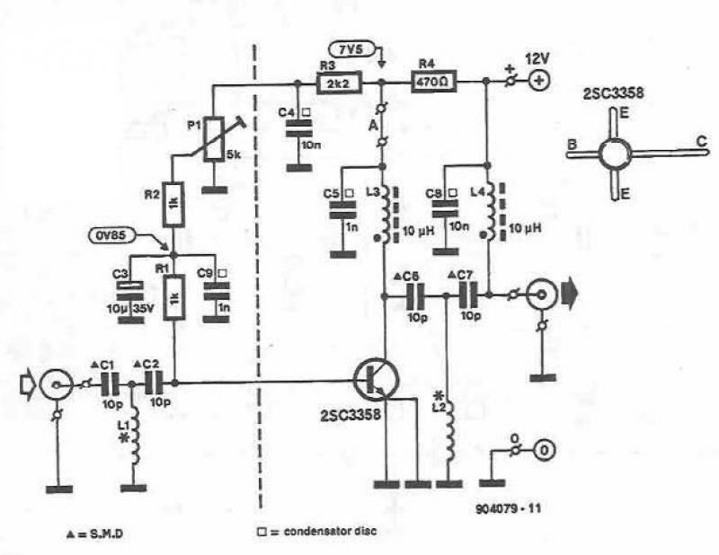
The overall bandwidth of the IF filter is approximately 150 Hz at -6 dB, provided that the NE592 operates within its linear range. It is important to note that under overload conditions, the bandwidth may broaden significantly; however, this scenario is unlikely during standard operation, where the amplifier typically processes weak input signals, as opposed to the stronger signals used during testing. This design ensures that the circuit remains effective in real-world applications, where signal strength can vary widely.In this circuit, an NE592 acts as an IF amplifier. DC coupling between mixer and amplifier is practical beacuse different + 6 V and + 12 V supply voltages are used. The voltage at the differential input is about 4.5 V. A narrow bandpass filter for the intermediate frequency is achieved using only one crystal as the reactive element.
Maximum IF gain is at the crystal series resonance, where the crystal impedance is very low. The capacitor across the amplifier input is intended to suppress mixing products that have a higher frequency than the IF. You cannot do without this cap because parasitic stray capacitance in parallel with the crystal causes unwanted amplification at frequencies higher than the crystal resonance, and thus degrades the IF selectivity.
Minor circuit modification is necessary if a ring diode mixer is used to drive the IF amp input. Transformer input is used for impedance matching. The 2 x 4.7 kOhm resistor voltage divider at the transformer secondary provides biasing (Ub/2) for both NE592 inputs. A single 4,7 kOhm resistor connected to a +6 V source would be an alternative arrangement. The parallel resonant circuit at the output is tuned to the IF frequency, and serves to attenuate unwanted skirt signals which are due to resonant poles adjacent to the crystal fundamental frequency.
A 100 ... 220 Ohm resistor in series with the crystal can be used to improve the filter skirt characteristic. The IF filter has a bandwidth of 150 Hz at -6 dB, provided the amplifier operates in its linear range. When overloaded, the bandwidth becomes much broader, but this does not happen during normal operation.
In a typical receiver the amplifier sees only weak input signals, as opposed to the tests carried out with stronger signals. 🔗 External reference
Related Circuits
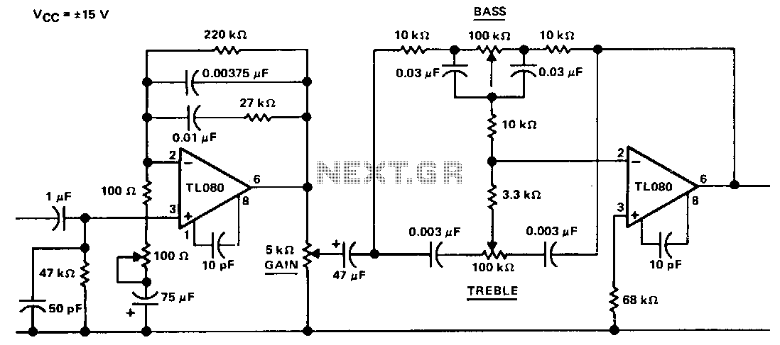
The circuit represents an "Americanized" version of the Baxandall negative-feedback tone control. At very low frequencies, the reactance of the capacitors is sufficiently high that they can be treated as open circuits, with the gain being regulated by the...
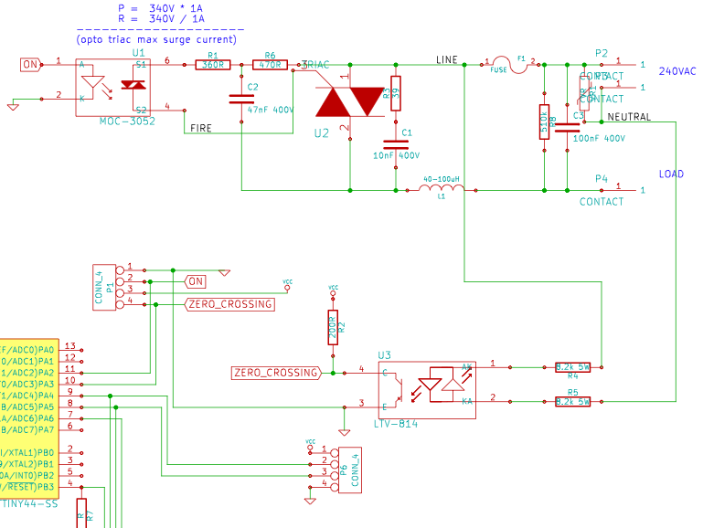
The resistance of the heater is constructed using 9 Ω nichrome wire with a diameter of 3 mm. When supplied with 240V (rms) voltage, this configuration results in a current of 25A (rms). Access to a mains line that...
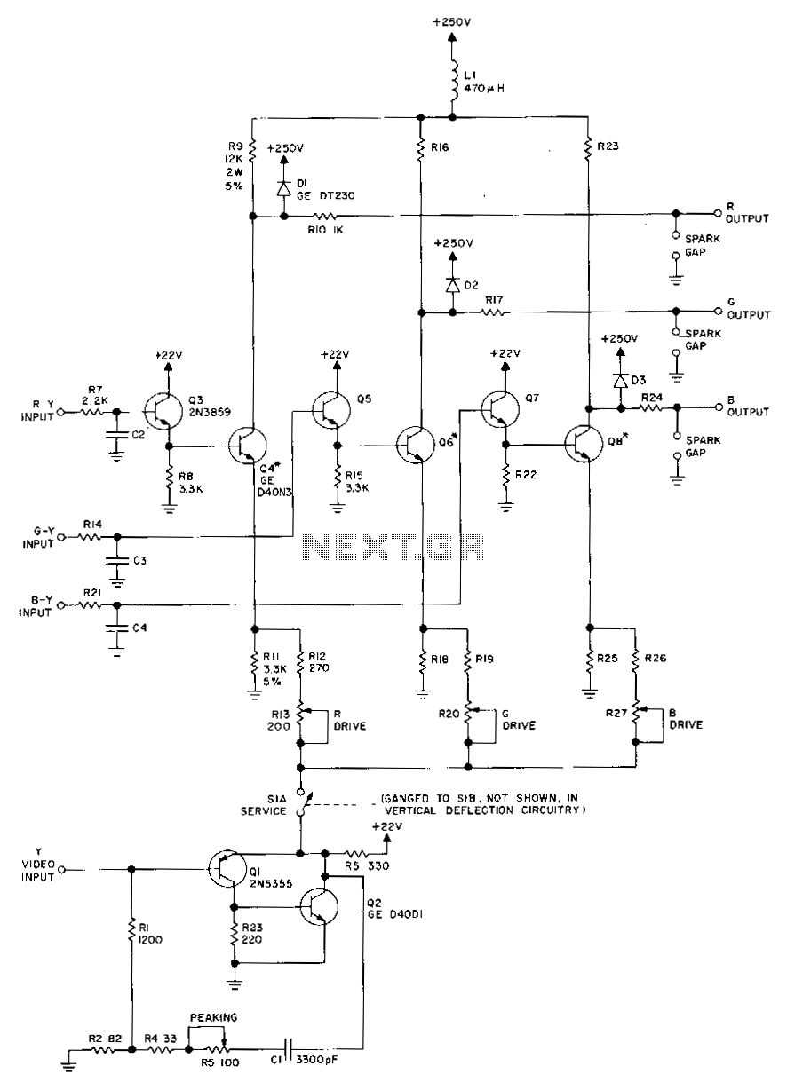
Transistors Q1 and Q2, along with their associated components, provide a low-impedance output necessary for driving the output stages. They enhance gain at high frequencies and improve video peaking for better transient response. Emitter followers Q3, Q5, and Q7...
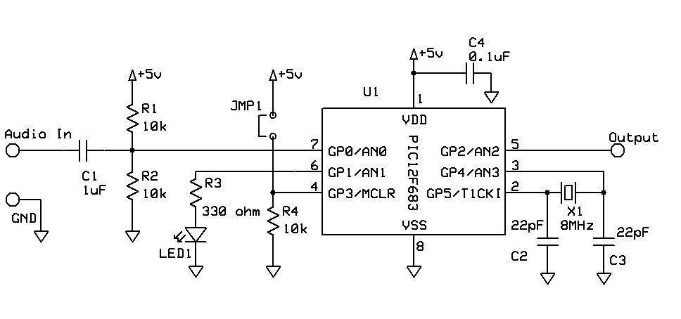
DTMF Touch Tone Decoder Using Microchip PIC Microprocessor. This project contains the details of using a Microchip PIC12F683 8-bit microprocessor to detect Dual-Tone Multi-Frequency (DTMF) signals. The DTMF Touch Tone Decoder circuit utilizes the Microchip PIC12F683 microprocessor, which is an...
This UHF amplifier circuit project is beneficial for enhancing weak TV signals. The amplifier provides a gain of 10-15 dB within a frequency range of 400 to 850 MHz. To ensure optimal performance and reliability, the PCB tracks should...
This design utilizes a well-established circuit topology for the power amplifier, employing a single-rail supply of approximately 60V and capacitor coupling for the speaker(s). The benefits for a guitar amplifier include a straightforward circuitry design, even for relatively high...