Polarity Indicator Circuit
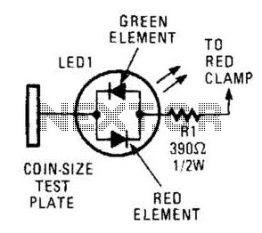
This circuit comprises a tri-color LED, a resistor, wire, and a coin-sized test plate. Two circuits must be constructed, one for each black clamp on a set of auto battery jumper cables. The circuits are installed inside the black clamps, utilizing wire lengths to connect to the red clamps. The initial step involves connecting one red clamp to the presumed positive post of the functioning battery. The test plate on the black clamp at the end of the cable should then be placed against the negative terminal of the good battery. The LED will illuminate red if the red clamp is incorrectly positioned. If this occurs, the clamp must be moved to the other post for verification. If the connection is correct, the LED will light green. The other black clamp should then be connected to the remaining post on the good battery, while the other red clamp is connected to the assumed positive terminal of the malfunctioning battery. The test plate on the remaining clamp should be touched to the engine block or a bare section of the dead car's frame. If the LED does not illuminate, the red clamp should be switched to the other terminal and tested again. When the LED glows green, the black clamp should be attached to the car's frame to prevent sparks near the battery. When disconnecting the clamps, they should be removed in reverse order to avoid sparks.
This circuit serves as a visual indicator for correct connections when jump-starting a vehicle, enhancing safety and ease of use. The tri-color LED is the focal point of the circuit, providing clear feedback on the status of the connections. The resistor is essential for limiting current to the LED, ensuring it operates within safe parameters.
The circuit can be designed using a simple series configuration where the LED and resistor are connected in series with the test plate. The circuit is powered through the jumper cable connections, allowing the LED to indicate proper or improper connections based on the polarity detected.
When constructing the circuit, careful attention should be paid to the wiring and soldering of components to ensure reliable operation. The use of insulated wire is recommended to prevent any accidental shorts. Additionally, the placement of the test plate should be easily accessible and clearly marked to facilitate quick and safe testing during the jump-start process.
In terms of functionality, the tri-color LED can be designed to light up in red when the polarity is reversed, providing immediate feedback to the user. A green light will indicate that the connections are correct, allowing the jump-start process to proceed safely. This design not only simplifies the jump-starting process but also minimizes the risk of damage to the vehicle's electrical system or personal injury due to incorrect connections.
In summary, the described circuit is a practical solution for enhancing the safety and efficiency of jump-starting a vehicle, utilizing visual indicators to guide users through the process. This circuit consists of a tri-color LED, a resistor, wire, and a coin-size test plate. You will have to build two such circuits one for each black clamp on a set of auto battery jumper cables. The author installed the circuits inside the black clamps themselves using lengths of wire to make the connections to the red clamps.
The first step is to connect one red clamp to what you believe is the positive post on the okay battery. Then, touch the test plate on the black clamp at the end of the cable to the negative terminal on the good battery.
The LED will light red if the red clamp is on the wrong terminal. If so move the clamp to the other post and check again. If all is well, the LED will light green. Pick up the other black clamp and connect it to the remaining post on the good battery. Connect the remaining red clamp to what you assume to be the positive terminal on the bad battery. Now, touch the test plate on the remaining clamp to the engine block or a bare area on the dead car`s frame. If the LED appears or doesn`t glow, switch the red clamp to the other terminal and test again. When the LED glows green, attach the black clamp to the car`s frame (which will prevent any sparks from occurring near the battery).
When you remove the clamps, take the clamps off in reverse order to avoid sparks. 🔗 External reference

