
flight computer

The revised design focuses on optimizing the overall weight and functionality of the system while maintaining robust performance. The single board design significantly reduces the complexity and weight of the assembly, allowing for a more efficient integration of components. The direct mounting of the battery onto the PCB eliminates additional connectors and wiring, which can contribute to weight and potential failure points.
The removal of the opto-coupler simplifies the circuit and reduces the number of components, thus improving reliability. Directly driving the actuator transistor with the microcontroller enhances response time and reduces latency in actuator control. The addition of the snubber diode across the motor protects against voltage spikes that can occur during motor operation, while the capacitor aids in filtering out high-frequency noise, ensuring stable operation of the microcontroller.
The decision to disable the brown-out reset feature is particularly crucial in environments where electrical noise may be present. This modification ensures that the microcontroller remains operational despite transient disturbances, which is vital for maintaining control during critical phases of operation.
The redesigned launch detection mechanism, utilizing a micro-switch activated by a sliding nail, provides a more reliable and shock-resistant solution. This change addresses previous issues where the armature could disengage upon impact, thereby enhancing the overall durability of the system during deployment.
The compact arrangement of the power, program, and arm switches not only simplifies user interaction but also contributes to aerodynamic efficiency by minimizing the profile of the rocket. The expansion of the selectable delay range is an important enhancement that allows for greater flexibility in operational timing, accommodating a wider variety of experimental setups.
Overall, these design improvements reflect a comprehensive approach to optimizing the system for performance, reliability, and ease of use in a compact form factor.The design changes were primarily chosen to improve weight of the system. The majority of weight savings were due to having a single board design, switching to single battery operation and mounting the battery directly on the PCB. Other small weight improvements included the use of smaller components. The opto-coupler has been removed and the micr o-controller directly drives the actuator transistor. A snubber diode has been added across the motor as well as a small capacitor to reduce noise. A capacitor has also been added across the micro-controller`s power rails. The software changes included disabling the brown-out reset on the micro-controller to prevent it from resetting when there was a bit of noise on the power rails. The "P" display during parachute deployment has been replaced with a "-" to reduce the amount of power drawn from the battery while the motor is in operation.
The launch detect switch is a smaller micro-switch and is activated by a large nail that slides within a guide. This helps prevent unnecessary shocks on the armature during landing. With the weight glued to the armature in V1. 2 it was possible for the armature to pop out of the switch on landing. The new arrangement is also more compact. The "power", "program" and "arm" switches have all been placed close together to allow them to be accessible from a much smaller hole in the rocket body.
This helps streamline the rocket reducing drag. Due to upcoming experiments the range of selectable delays has also been increased. The following table gives the range of delays settable with version 1. 3. 🔗 External reference
Related Circuits
BattMan II is a computer-controlled battery manager designed for typical rechargeable batteries utilized by R/C and electronics hobbyists, as well as various consumer product batteries. BattMan II supports Nickel-Cadmium (NiCd), Nickel-Metal-Hydride (NiMH), Lithium-Ion (Li-Ion), Lithium-Polymer (LiPo), Lithium-Nano-Phosphate (LiNP), and...
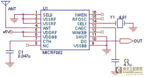
The maximum coverage of the RSR232 serial port transport protocol is 10 meters, which poses significant challenges for remote transmission control. To address this issue, a design has been developed utilizing ultra-high frequency (above 300 MHz) for transmission. This...
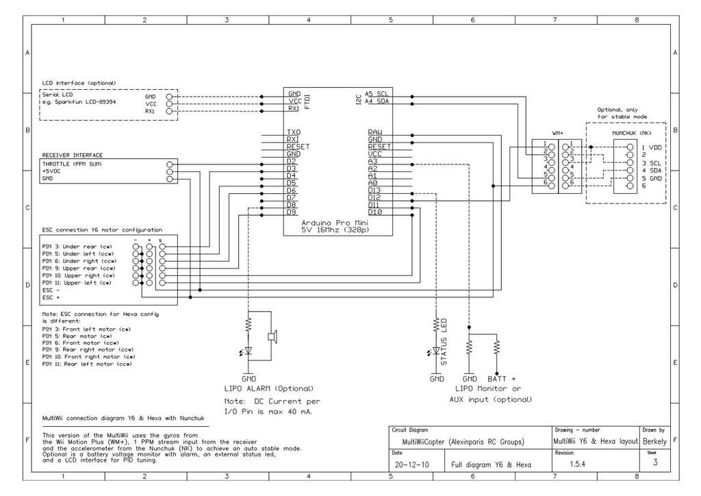
This is a video showcasing a test flight of the Quad Rotor Observer (QRO) v8, which is equipped with the FCWii board, Wii Motion Plus gyroscopes, and Nunchuk accelerometers. The Quad Rotor Observer (QRO) v8 is an advanced quadcopter designed...
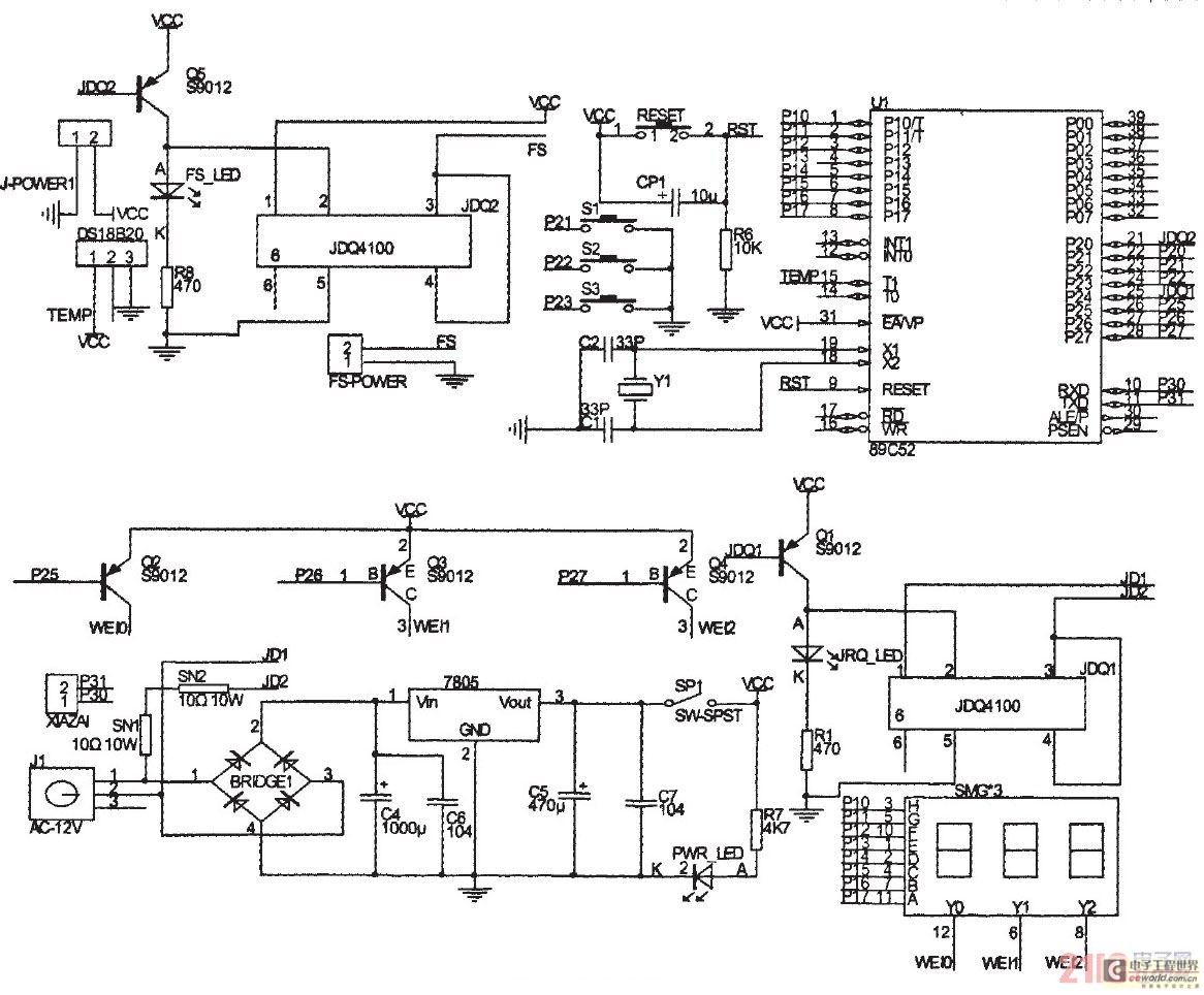
The primary principle of the system is to gather real-time temperature data from a temperature sensor using a microcontroller, which then compares this data with pre-defined thermostat values to maintain the desired temperature within a sample container. This text...
A VU meter from a SONY double tape deck, model number "SONY TC-W230," has been salvaged and is intended to be integrated into a computer tower case. The process begins with identifying the connections on the printed circuit board,...
This circuit is a stable frequency counter with an accuracy of 5 significant digits. It operates within a frequency range of 0 to 30 MHz and has an input sensitivity greater than 100 mV. The probe connects to the...