
adding vu meter to your computer
The integration of the VU meter into the computer tower case involves several steps and considerations to ensure proper functionality and aesthetics. The first step is to carefully remove the VU meter from the SONY TC-W230 tape deck, ensuring that the connections to the CXD1017 IC are preserved for later use. The identification of the wire connections is crucial, as these will be used to interface the VU meter with the computer's audio output.
The replacement of the original incandescent lamps with four white LEDs is a significant modification aimed at reducing power consumption while maintaining adequate illumination for the LCD display. The LEDs should be selected based on their forward voltage and current ratings to ensure compatibility with the existing circuit. A suitable resistor may be required in series with the LEDs to limit the current, thereby preventing damage.
Testing the VU meter prior to installation is essential, particularly because it was salvaged from older audio equipment. A simple test circuit can be constructed to apply the necessary power supply voltages and audio signals to verify that the VU meter responds correctly to audio input. This can be done by connecting the meter to a known audio source and observing the movement of the needle in response to varying audio levels.
For the audio connection, an adapter circuit is required to connect the computer's audio output to the Hi-Fi system's RCA inputs. This adapter can be constructed using a standard 3.5mm jack connector and two RCA connectors. The wiring should be done in parallel, ensuring that the left and right audio channels are correctly connected. Proper shielding and grounding techniques should be employed to minimize noise and interference in the audio signal.
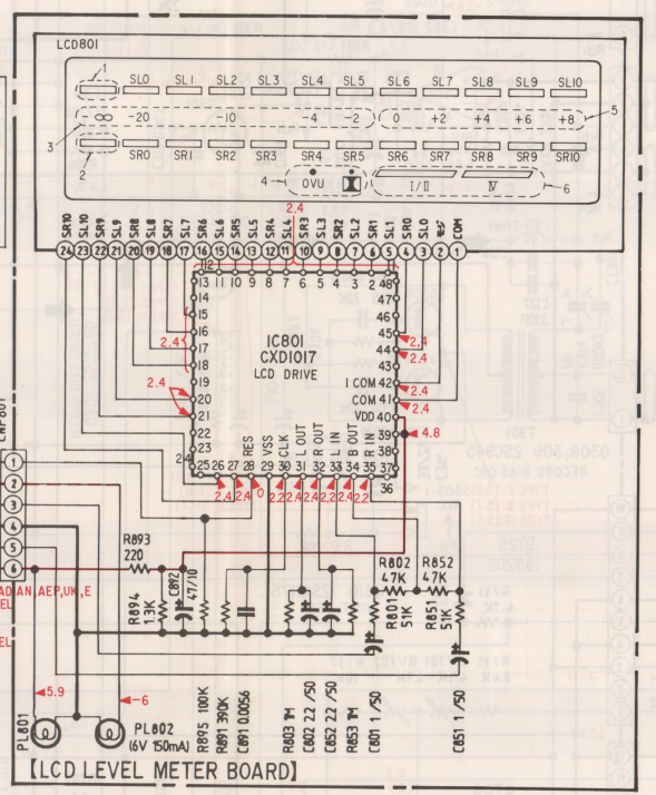
Overall, the project involves careful planning and execution to successfully integrate the VU meter into a modern computer setup while preserving its functionality and enhancing the aesthetic appeal of the computer tower.From a SONY double tape decks with model number "SONY TC-W230" I have picked a nice LCD VU-meter. I have decided to add it to my computer tower case. the following steps explain how to do this. this is based on IC lablelled CXD1017 (impossible to find a datasheet) on the printed circuit it is easy to identify the connected wires (second photo redrectangle) so we can see: The first think that I have done is to look for the schematic circuit of this HIFI equipment and after a long time I have filnally found the service manual. So the following photo shows the VU-Meter schematic diagram: The lapms used in the VU-Meter to lighten the LCD consume a lot of current this why they are powered by a symetric source -6V and 6V.
I have decided to replace them with 4 white LEDS. Before I have decided to mount the VU-Meter I have decided to test it because I have picked it from salvaged audio equipement and I don`t know if it function or not. As my computer is connected the AUX input of my HI-FI system via RCA connectors I have to add an adaptor to convert the audio channel from jack connector of the computer sound card to RCA connectors going to the HI-FI system.
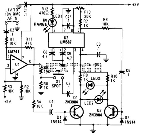
this circuit is a simple parallel connexion between jack connector and RCA connectors. 🔗 External reference
Related Circuits
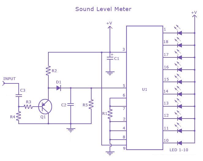
This is a single-chip sound level meter that can be used to display the sound level of an amplifier or simply the sound level from a microphone. The core component of the circuit is the IC LM3915 Audio Level...
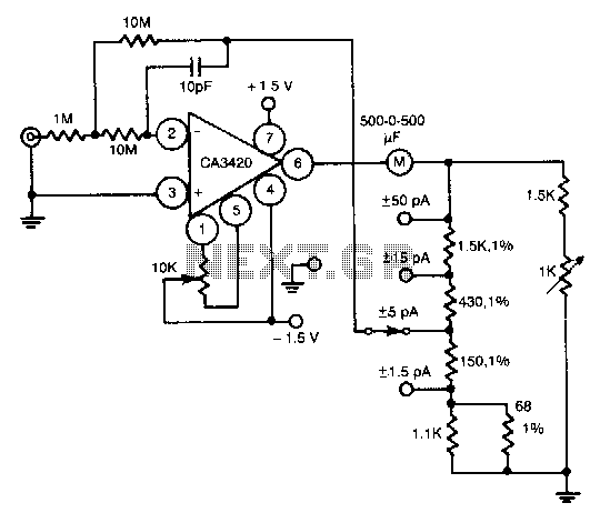
This circuit utilizes the exceptionally low input current of 0.1 pA from the CA3420 BiMOS operational amplifier. It employs a single 10-MΩ resistor. The circuit operates within a range of ±50 pA, achieving a maximum full-scale sensitivity of ±1.5...
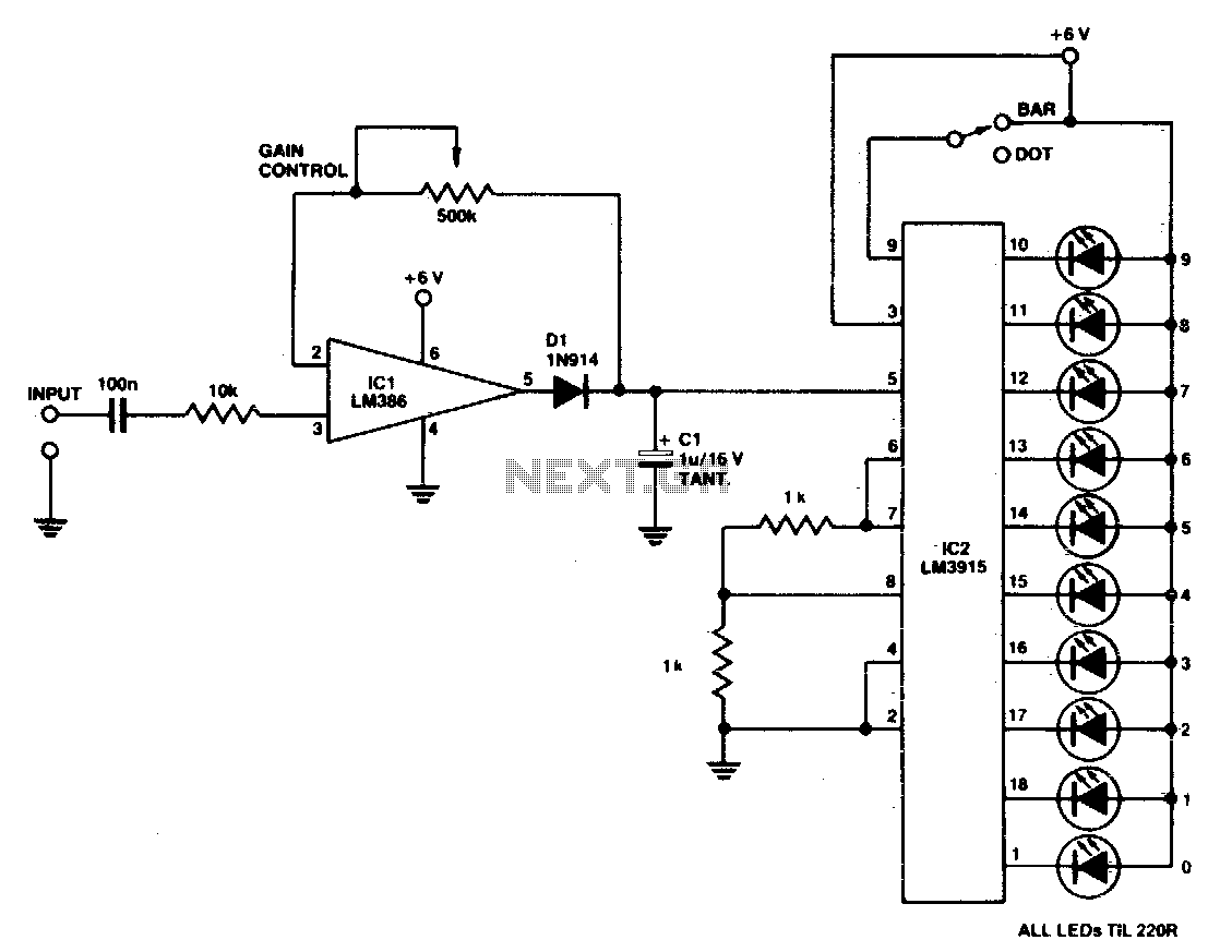
A simple power meter can be configured to provide a bar or dot display for a hi-fi system. Green LEDs are used for levels 0 to 7, yellow for level 8, and red for levels 9 to indicate peak...
The use of diode rectifiers in AC voltmeters with a low lower limit of measurement range (0.5-1 V) leads to significant nonlinearity of the scale due to the nonlinearity of the current-voltage characteristics of diodes. The incorporation of electronic...
This meter is unique as it does not utilize a D'Arsonval movement or digital display for frequency readings. Instead, the measured frequency is indicated on a hand-calibrated dial. Any audio signal applied to the circuit is amplified by U1,...
The circuit is a comparator that can measure the voltage of a car battery in steps of 1 Volt. The voltage is determined after comparing the voltage of the battery, which is applied to the inverting inputs of amplifiers,...