
Quadcopter flight with the FCWii board and the Wii Motion Plus and Nunchuk MEMS sensors.

The Quad Rotor Observer (QRO) v8 is an advanced quadcopter designed for enhanced stability and maneuverability during flight. The integration of the FCWii flight control board allows for precise control and responsiveness, making it suitable for various applications, including aerial photography and recreational flying.
The use of Wii Motion Plus sensors, which incorporate gyroscopes, provides real-time orientation data, enabling the quadcopter to maintain its balance and stability in the air. This is crucial for achieving smooth flight dynamics, especially during rapid movements or when encountering wind disturbances.
Additionally, the Nunchuk accelerometers contribute to the quadcopter's ability to sense changes in speed and direction, further enhancing the overall flight performance. Together, these components work in tandem to ensure that the QRO v8 can execute complex maneuvers while maintaining stability.
The video serves as a demonstration of the quadcopter's capabilities, showcasing its responsiveness to pilot inputs and its ability to perform agile movements. This test flight highlights the effectiveness of the chosen components and their contribution to the quadcopter's overall functionality.
In summary, the QRO v8 represents a significant advancement in quadcopter design, leveraging the latest in motion sensing technology to deliver an exceptional flying experience.Here a video of a test flight of my Quad Rotor Observer (QRO) v8 with the FCWii board and the Wii Motion Plus (gyroscopes) + Nunchuk (accelerometers) MEMS. 🔗 External reference
Related Circuits
The enable signal for the USB chip and GLCD controller is generated by a PLD decoder from the address lines. The memory map for the I/O of the 8051SBC board indicates that the available space ranges from 0x0300 to...
Most individuals seeking to modify and enhance their Spectrum often focus on the keyboard as a primary area for improvement. However, a straightforward replacement requires opening the computer, which can be discouraging for two main reasons. Firstly, this action...
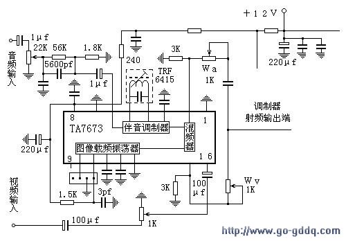
The circuit design philosophy allows for debugging without any RF instruments. Although its performance may not match that of professional equipment, it should be adequate for hobbyists, with audio-visual transmission effects comparable to general-purpose machines. The transmitter consists of...
Ensure to verify all connections utilizing the circuit diagram and breadboard schematic available for download from the provided links. This resource can assist during the assembly process. To create a reliable electronic circuit, it is essential to meticulously verify all...
One of the more challenging aspects of creating a control or security system that utilizes a PC, such as a burglar alarm, is connecting the sensors to the computer. This typically requires specialized interface expansion boards, and programming that...
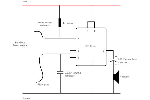
A client required a timer to keep their DVR activated and recording when the IR motion detector output a pulse. The timer needed to maintain a low signal level for a specified duration upon motion detection. However, it was...