
flip flop relay

The flip-flop relay circuit using a 555 IC is designed to alternate the activation of two relays, providing a reliable mechanism for switching applications. The circuit operates in astable mode, where the 555 timer generates a square wave output that toggles the state of the relays.
The primary components of the circuit include the 555 timer IC, two relays, resistors, capacitors, and a power supply. The 555 timer is configured with external resistors and capacitors to set the frequency of the oscillation. The output pin of the 555 timer is connected to the control terminals of the relays, allowing them to switch on and off in a predetermined sequence.
In astable mode, the 555 timer continuously charges and discharges the timing capacitor, creating a square wave signal. The frequency of this signal can be adjusted by varying the values of the resistors and capacitors in the timing network. This flexibility allows the user to customize the switching speed of the relays based on the application's requirements.
The relays act as electrically operated switches, capable of controlling larger loads. When the output of the 555 timer goes high, it energizes the first relay, closing its contacts and allowing current to flow through the connected load. After a brief interval, the output goes low, de-energizing the first relay and energizing the second one, effectively alternating the control between the two relays.
This flip-flop relay circuit can be employed in various applications, such as automated lighting systems, motor control, or any scenario where sequential relay operation is desired. The simplicity of the design, coupled with the versatility of the 555 timer, makes this project an excellent choice for both educational purposes and practical implementations in electronics.A very useful, easy and interesting project of a flip flop relay circuit using a 555 IC. The circuit will continously flip flop or on and off two relays one by one. .. 🔗 External reference
Related Circuits
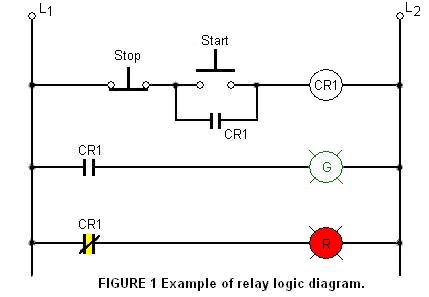
The relay logic circuit creates an electrical schematic diagram for controlling input and output devices. Components include resistors, capacitors, and others. The relay logic circuit operates by utilizing electromechanical relays to control various input and output devices in a systematic...
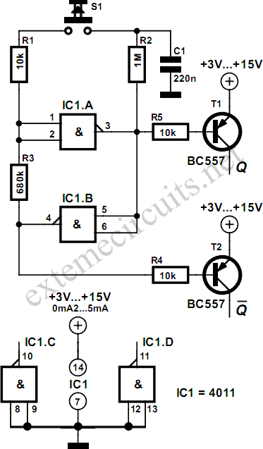
Using just two NAND or inverter gates, it is possible to build a D-type (or toggle) flip-flop with a push-button input. At power-up, the output of gate N2 is at a logical 1, ensuring that transistor T2 is switched...
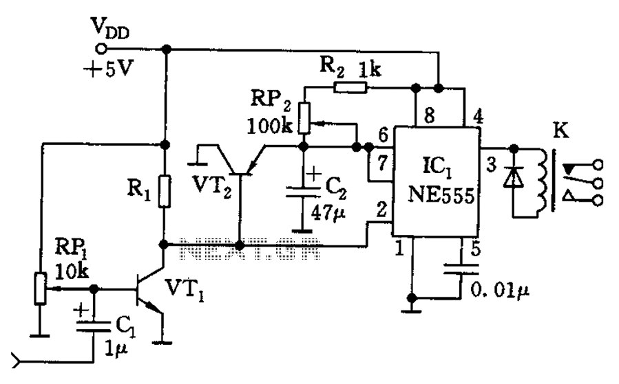
The circuit consists of a sound detection circuit and a monostable trigger circuit that activates a relay. VT1 amplifies the input audio signal. When a signal is detected, the 555 timer is triggered, pulling K. Simultaneously, VT2 conducts, allowing...
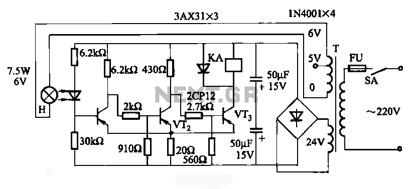
JG series of photoelectric relay circuit. To ensure reliable operation, a Schmitt trigger circuit has been incorporated. These circuits function similarly; when light strikes the photosensitive component, its internal resistance decreases, activating the transistor VT and subsequently energizing the...
Remove the 6 mm screw that secures the lower rear fairing cover. This cover is the black plastic piece to which the spark plug protectors are attached. Only the machine screw should be removed; do not detach the lower...
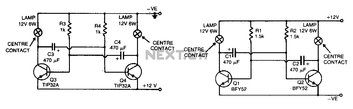
The flashing action is generated by a basic astable multivibrator configured to produce a flashing rate of approximately 60 flashes per minute for each lamp. The circuit designed for positive earth systems employs NPN transistors, while alternative configurations utilize...