
Know About The Relay Logic

The relay logic circuit operates by utilizing electromechanical relays to control various input and output devices in a systematic manner. This type of circuit typically includes several key components such as resistors, capacitors, and relays, which work together to manage electrical signals.
In this circuit, relays serve as switches that can open or close electrical contacts in response to an input signal. When a voltage is applied to the relay coil, it generates a magnetic field that activates the relay, allowing current to flow through the output circuit. This mechanism is crucial for controlling devices such as motors, lights, or alarms based on specific input conditions.
Resistors in the circuit are used to limit current flow, ensuring that components operate within their specified voltage and current ratings. Capacitors may be included to filter signals, providing stability and reducing noise in the circuit. Additionally, the configuration of the relay logic can be designed to create complex control sequences, allowing for multiple inputs to influence a single output or vice versa.
The schematic diagram of a relay logic circuit typically represents these components with standardized symbols, making it easier to understand the circuit's operation. The layout will illustrate how the components are interconnected, showing the paths for both input signals and the resulting output actions. This clarity is essential for troubleshooting and maintaining the circuit.
Overall, the relay logic circuit is a versatile solution for automating control processes in various applications, from industrial machinery to home automation systems. The careful selection and arrangement of components within the schematic are vital for achieving reliable and efficient operation.The relay logic circuit forms an electrical schematic diagram for the control of input and output devices. Component: Resistor, Capacitor, .. 🔗 External reference
Related Circuits
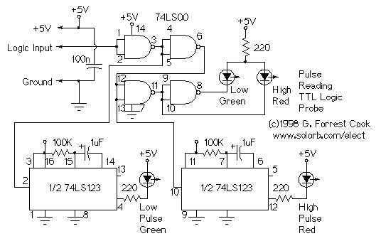
This circuit uses LEDs to display logic states for high, low, rising pulse, and falling pulse. It is generally useful for debugging logic circuitry. The described circuit employs light-emitting diodes (LEDs) as visual indicators for various logic states in digital...

The schematic below illustrates four methods of controlling a relay with a digital logic signal. Figure A can be used in most cases where the relay coil requires 100 mA or less and the input current is 2 milliamps...

An NPN bipolar transistor is typically utilized for relay switching, particularly with 12V coil-rated relays, as it helps maintain circuit separation. A diode is also added to prevent issues. The necessity of driving the relay with a transistor depends...
A logic indicator circuit, also known as a logic probe, is utilized to identify the logic level at any point within a logic circuit. The indicator can be visual, employing components such as LEDs, LCDs, or seven-segment displays. The logic...
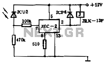
The circuit operates as a photoelectric switch utilizing a photoresistor. It exhibits high sensitivity, particularly in controlling a light relay. Under low illumination, the transistor (VT) remains non-conductive. When the illumination reaches a certain threshold, the resistance of the...
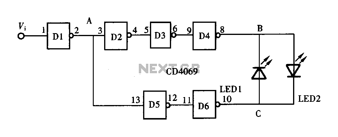
A logic pen, also known as a logic detection probe, is a commonly used tool for detecting the logic state at various points within digital circuits. The logic states in digital circuits are typically categorized into three types: a...