
flipflop What happens when theres no specific input variable on a logic diagram using a JK flip flop

A state machine can be effectively represented using a state transition table and a corresponding state diagram. In this case, Q1 and Q2 are the two state variables of the JK flip-flop, which can exist in four possible states: 00, 01, 10, and 11. The state transition table should be structured with the following columns: Current State (Q1, Q2), Next State (Q1', Q2'), and Clock Pulse.
The left side of the table will enumerate the current states of Q1 and Q2. For instance:
- State 1: Q1 = 0, Q2 = 0
- State 2: Q1 = 0, Q2 = 1
- State 3: Q1 = 1, Q2 = 0
- State 4: Q1 = 1, Q2 = 1
The right side will represent the next states that Q1 and Q2 will assume after the next clock pulse. The transitions depend on the behavior of the JK flip-flop, which toggles its output based on the inputs J and K, as well as the current state.
For example, if the current state is 00 and the inputs to the JK flip-flop are set to J=1 and K=0, the next state will be 01. Conversely, if J=0 and K=1, the next state would transition to 10. The complete table will thus detail each transition based on the current state and the inputs.
When constructing the state diagram, the nodes will represent the states (00, 01, 10, 11), and directed edges will indicate the transitions between these states based on the input conditions. It is common practice to label the edges with the input conditions that trigger the state transitions, but in certain scenarios, such as focusing solely on state progression, these labels can be omitted for clarity.
This comprehensive approach to documenting the state machine provides a clear understanding of the operation of the JK flip-flop and its state transitions, facilitating further analysis and design of more complex sequential circuits.Q1 and Q2. to form a table, on the left side, list the the four possible states of Q1, Q2; on the right side, write the values that Q1 and Q2 will assume after the next clock pulse. The table will then contain a complete description of the state machine. JustJeff May 26 `11 at 0:53 thanks. when there`s a diagram like this, would you assume the output is the Q` on the right-hand JK flipflop On the other one`s i`ve seen it usually specifically shows the output. I need to make a state diagram, so would I just omit the intput/output value that`s usually included on the paths between the nodes
🔗 External reference
Related Circuits
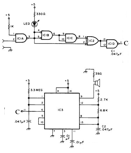
The NE556 timer can function as an indicator for the static state of a digital logic audible terminal. An audible logic probe is beneficial for visually inspecting a component while simultaneously checking the logic state at another point far...
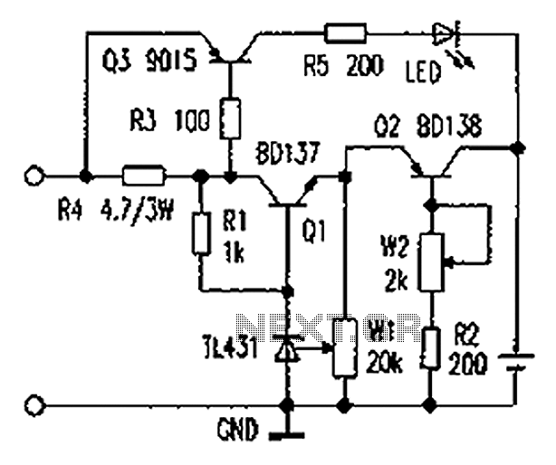
As illustrated in the figure, the lithium battery charging control board employs a constant current charging mechanism. The components Q1, R1, W1, and TL431 form a precision adjustable voltage regulator circuit. The components Q2, W2, and R2 create an...
The following circuit illustrates the iButton Electronic Lock Schematic diagram. This circuit is based on the Atmel AT89C2051 integrated circuit (IC). Features include an onboard power supply comprising a transformer (T1) and a voltage regulator (U4), a bridge rectifier...
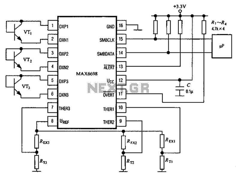
Channel 7 presents a circuit diagram of a smart temperature sensor using the MAX6698. This circuit includes three transistors (VT1, VT2, and VT3) and three thermistors (RT1, RT2, and RT3). An internal reference voltage source is provided via resistors...
A newcomer is seeking a welcoming environment and expresses a desire to share a considerable amount of information. In the context of electronic schematics, it is essential to facilitate an inclusive environment for individuals at all levels of expertise. This...
Volvo S40 Wiring Diagram Radio 1997 Manual PDF Download. The Volvo S40 wiring diagram for the radio from the 1997 model year provides a detailed schematic representation of the electrical connections and components involved in the vehicle's audio system. This...