
iButton Electronic Lock Schematic Diagram
The iButton Electronic Lock circuit is designed to provide a secure locking mechanism controlled by a microcontroller, specifically the Atmel AT89C2051. This microcontroller serves as the core processing unit, executing the logic required to manage the locking system based on inputs from the iButton device.
The power supply section of the circuit is essential for ensuring stable operation. The transformer (T1) steps down the mains voltage to a lower AC voltage, which is then rectified by the bridge rectifier (VD9-VD12). This rectification process converts the AC voltage into a DC voltage suitable for powering the microcontroller and other components. The voltage regulator (U4) is employed to maintain a constant voltage level, which is critical for the reliable operation of the microcontroller and associated circuitry.
The circuit is designed to operate at a current of 20mA, which is sufficient for the microcontroller and peripheral devices without overloading the power supply components. The battery pack (BT1-BT10) consisting of AA batteries provides an alternative power source, ensuring that the lock remains operational even during power outages.
The ADM1232 IC plays a crucial role in the circuit by managing the reset pin of the microcontroller. This ensures that the microcontroller starts in a known state and can recover from any unforeseen issues, enhancing the overall reliability of the locking mechanism.
Other components in the circuit, such as capacitors, resistors, transistors, and diodes, are used for filtering, signal conditioning, and switching applications, which contribute to the overall functionality and efficiency of the electronic lock system. The inclusion of these components allows for improved noise immunity and ensures that the circuit operates smoothly under various conditions.
Overall, the iButton Electronic Lock circuit is a well-designed system that integrates various electronic components to achieve a secure and reliable locking mechanism, suitable for various applications requiring enhanced security measures.The following circuit shows about iButton Electronic Lock Schematic diagram. This circuit based on the Atmel AT89C2051 IC. Features: power supply on board (transformer T1, voltage regulator U4), bridge rectifier VD9-VD12, 20mA current, BT1-BT10 AA batteries, ADM1232 IC for mcu reset pin control, Component: IC, Capacitor, Resistor, Tra nsistor, Diode, Transformer. [high-voltage-lab. com] 🔗 External reference
Related Circuits
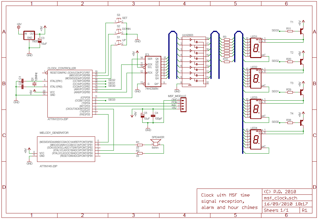
The National Physics Laboratory broadcasts a time signal, previously known as the Rugby clock but now called "Time from NPL." Its most commonly known as the MSF signal due to it originally being identified in Morse code those letters....
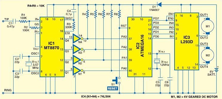
Mobile robot schematic diagram for a cellphone-controlled robot. Detailed modules used for the cellphone-controlled mobile robot include: DTMF Decoder: MT8870/CM8870; Microcontroller: ATMEGA16; Motor Driver: L293D; Actuator: DC Motor 5-6V. The mobile robot schematic diagram is designed for operation via a...
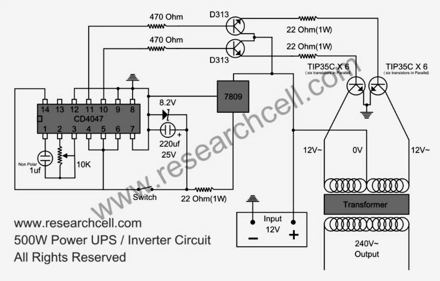
This circuit diagram features a single variable resistor utilized to adjust the frequency of a 240V AC output current. It is advisable to use a frequency meter to modify the frequency from 50Hz to 60Hz according to specific requirements....
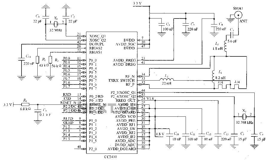
Figure C1 and C2 depict a 22 pF capacitor connected to a 32 MHz crystal oscillator circuit, which utilizes a quartz crystal for standard operation. Capacitors C3 and C4, each rated at 15 pF, are connected to a 32.768...
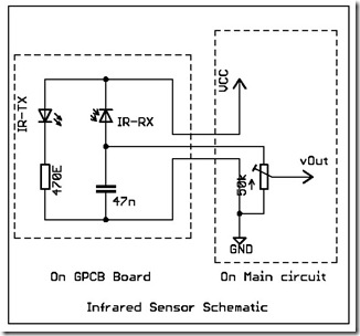
The following circuit illustrates a simple infrared sensor module circuit diagram. Features include a simple infrared sensor module and flame detection. The simple infrared sensor module circuit operates by utilizing an infrared (IR) transmitter and receiver pair. The IR transmitter...
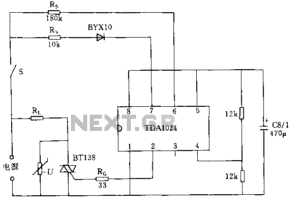
The circuit switch S closes when the integrated circuit TDA1024 is activated. A trigger pulse is generated by the zero crossing of the mains voltage, allowing a bidirectional thyristor to conduct full current through the load Rl. When switch...
Warning: include(partials/cookie-banner.php): Failed to open stream: Permission denied in /var/www/html/nextgr/view-circuit.php on line 713
Warning: include(): Failed opening 'partials/cookie-banner.php' for inclusion (include_path='.:/usr/share/php') in /var/www/html/nextgr/view-circuit.php on line 713