
Floating 9V Supply For DVM Modules
The described digital voltmeter (DVM) module represents a practical solution for integrating an LCD readout into various test and measurement equipment. The use of the ICL7106 A-D converter chip facilitates accurate voltage measurements, essential for laboratory and industrial applications. The necessity for the LCD module to float relative to the PSU supply rails is a critical design consideration, ensuring that the voltmeter can operate independently from the power supply's ground reference.
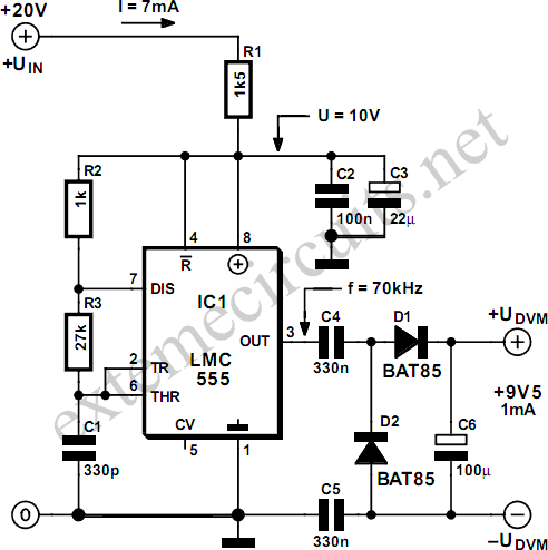
The astable multivibrator configuration of the TLC555, LMC555, or 7555 timer IC is a robust choice for generating a stable square wave signal. Operating at 70 kHz, this square wave is suitable for rectification and subsequent voltage regulation. The rectifier circuit, likely composed of diodes, converts the AC square wave into a pulsating DC voltage, which is then smoothed by the capacitors C5 and C6. These capacitors not only serve to filter the rectified output but also provide the necessary isolation, protecting the DVM module from fluctuations in the PSU supply voltage.
The recommendation against using the older NE555 IC is significant, as its higher current draw could compromise the performance of the voltage converter. The adjustment of resistor R6 is a crucial step in ensuring that the CMOS 555 operates within its optimal voltage range, allowing for reliable performance. The output current specification of 1 mA at 9.5 volts indicates that the converter is designed to meet the power requirements of the LCD module effectively while maintaining efficiency.
In summary, this circuit design exemplifies a well-considered approach to integrating a digital voltmeter into power supply systems, emphasizing the importance of electrical isolation, component selection, and circuit stability.Most commercial DVM modules with an LCD readout are 9-V powered and based on an ICL7106 or similar A-D converter chip. These modules are typically used in laboratory power supplies and other test and measurement equipment where a drop-in solution needs to be found to realize a voltmeter readout.
Particularly in power supply units, the LCD module w ill need to float` relative to the PSU supply rails, and this inevitably requires a separate 9-volt power supply. In some cases, batteries may be used but these have distinct advantages. The alternative, a 9-V converter effectively powered by the PSU and yet‚oating, is shown here. It is built from the ubiquitous TLC555, LMC555 or 7555) timer IC acting in astable multivibrator conguration producing a 70-kHz square wave fed into a simple rectifier.
In essence, capacitors C5 and C6 afford the above mentioned electrical isolation between the PSU supply rails and the LCD module. The old, bipolar NE555 IC should not be used here because it presents a too heavy loads on the converter`s own supply voltage.
Depending on the exact type and brand of the CMOS 555 you`re using, resistor R6 may need to be redimensioned a bit to ensure a supply voltage of about 10 volts at pins 8 and 4 of the chip. At an output voltage of 9. 5 V, the maximum output current of the converter s about 1 mA. 🔗 External reference
Related Circuits
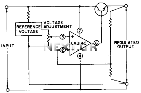
The circuit utilizes a CA3140 BiMOS operational amplifier that is capable of providing a regulated output adjustable from approximately 0 to 24 volts. The circuit is fully regulated. The CA3140 BiMOS operational amplifier is a versatile component that combines the...
This chapter provides detailed schematics of various power supplies suitable for use with common Ar/Kr ion tubes available to hobbyists in the surplus market. Included are examples of commercial designs (Omnichrome 150R and 532 head, Lexel 88 and head)...
Proposed power supply for amplifier 100W v-mosfet is what appears in the above form. It has separated supply for the various stages of supply, stage for power, stage for control, supply for preamplifier and for stage of protection. Whoever...
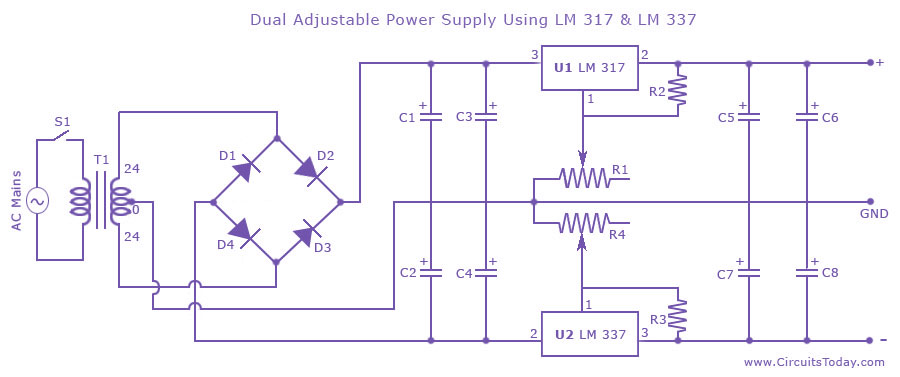
Dual adjustable power supply circuit with a diagram using IC LM317 and LM337. This variable power supply circuit has a range of 1.2 volts to 30 volts. The dual adjustable power supply circuit utilizes the LM317 and LM337 voltage regulators...

This schematic represents a radio receiver circuit based on the TDA7088T, which is suitable for use in mono portable and pocket radios. The TDA7088T is a bipolar integrated circuit designed to operate with a minimal number of peripheral components...
The MAX34446 data logger for power supplies is capable of monitoring voltages for overvoltage and undervoltage conditions, as well as overcurrent and overtemperature situations. The device continuously checks user-programmable thresholds. The MAX34446 is an advanced monitoring solution designed for power...