
FM Radio Receiver Circuit for Battery Supply

The TDA7088T is a versatile integrated circuit that facilitates the design of compact and efficient radio receiver systems. Its architecture allows for the implementation of a Frequency-Locked Loop (FLL), which is crucial for maintaining stable frequency tuning and minimizing drift. The use of an Intermediate Frequency (IF) of around 70 kHz is standard in many radio applications, as it strikes a balance between selectivity and sensitivity.
The circuit design emphasizes the importance of using active RC filters, which enhance selectivity by allowing only the desired frequency range to pass while attenuating unwanted signals. This is particularly beneficial in environments with multiple signal sources, as it helps to reduce interference and improve overall audio clarity.
Furthermore, the mute circuit integrated within the design plays a vital role in enhancing the user experience by eliminating background noise during periods of weak signal reception. This feature ensures that only clear audio signals are amplified, thus providing a more enjoyable listening experience.
The choice of the TDA7088T is driven by its ability to operate effectively with a minimal number of external components, making it an ideal solution for portable applications where space and cost are critical factors. The design can be easily adapted for various radio frequency bands, allowing for flexibility in application while maintaining performance standards. Overall, this schematic serves as a foundation for developing efficient and reliable radio receiver circuits suitable for consumer electronics.This is a schematic for radio receiver circuit. This circuit is based on the TDA7088T that can be used in mono portable and pocket radios. This is a bipolar integrated circuit. This is the figure of the circuit; When a minimum of peripheral components (of small dimensions and low cost) is important, we can use TDA7088T. Frequency-locked -loop (FLL ) system with an Intermediate Frequency (IF) of about 70 KHz is built on this circuit. By active RC-filters, selectivity is achieved. De-tuning related to the IF and the mute circuit is suppress too week input signals. [Schematic circuit source: NXP Semiconductor Application Notes] Disclaimer All files are found using legitimate search engine techniques. This site does not and will not condone hacking into sites to create the links it list. We will and do assume that all links found on the search engines we use are obtained in a legal manner and the webmasters are aware of the links listed on the search engines.
If you find a URL that belongs to you, and you did not realize that it was "open to the public", please use the report button to notify the blogmaster of your request to remove it or it will remove within 24 hours. This is not an invitation for webblog haters to spam with requests to remove content they feel that is objectionable and or unacceptable.
Proof of URL ownership is required. NOTICE: This Blog Has Already Been Reviewed And Accepted By Blogger. com 🔗 External reference
Related Circuits
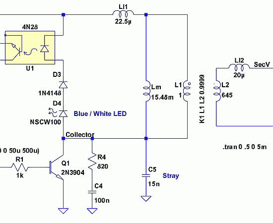
Since then, NL has evolved into the Microsoft Windows®-based NL4, which has been extensively used by world-class engineers in various fields of electronics for almost 10 years. NL5 is the first version to be publicly available. Unlike conventional SPICE-based...
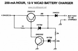
This NiCAD battery charger circuit charges the battery at 75 mA until it is fully charged, after which it reduces the current to a trickle rate. It can completely recharge a dead or unpowered battery in 4 hours, and...
This circuit is designed for use with inductive pick-up elements and dynamic microphones. Most soundcards feature a line input and a separate input for electret (condenser) microphones. To connect an inductive tape recorder head or a dynamic microphone, an...
The SSY-1 is a compact pulsed Nd:YAG laser that was initially utilized as part of the laser rangefinder in the M1 Abrams tank. The laser head and PFN-1 pulse forming network, which includes a flashlamp capacitor, inductor, and diode,...
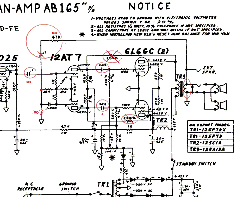
The Fender Bassman is a legendary guitar amplifier recognized by both guitar and bass players. Introduced in 1951, it was primarily aimed at bass guitar players and marketed as a bass amplifier for the Fender Precision Bass guitar, the...
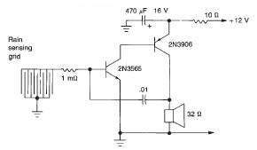
This rain detector electronic circuit project is a simple alarm circuit that activates an audio warning when liquid is detected on the sense pad. The circuit diagram is based on two transistors. When the sense pad conducts, transistors Tr1...