
Flooding rats Electronic cat

This circuit operates as a timer that generates periodic cat sounds to deter pests. The NE555 timer is configured in astable mode, allowing it to continuously switch between high and low output states. The timing interval, which dictates how long the LED remains on and how often the cat call is emitted, can be adjusted by changing the values of the resistors R1, R2, and the capacitor C1. The potentiometer RP allows for fine-tuning of the charging time, thus influencing the overall frequency of the output sound.
The KD-5605 integrated circuit is a sound generator that produces the desired cat call sound. Its output is connected to a power amplifier (IC3), which boosts the signal to drive a speaker (BL). This amplification is crucial for ensuring that the sound is loud enough to be effective in scaring away rodents.
The feedback loop created by the charging and discharging of capacitor C1 is essential for the continuous operation of the circuit. The internal discharge of the NE555 timer ensures that the capacitor discharges fully, allowing for a consistent timing cycle. This self-sustaining mechanism is what makes the circuit efficient for long-term operation without the need for constant manual intervention.
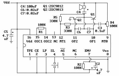
In summary, this electronic circuit effectively combines a timer, sound generation, and amplification to create a pest deterrent system that is both practical and adjustable based on the user's requirements. The design is straightforward, making it suitable for various applications where pest control is necessary.Electronic circuit shown in Figure cat. ICl time base integrated circuit NE555, it potentiometer RP, resistor Rl, R2 and capacitor Cl form time control circuit for controlling mew interval. IC2 is mew IC KD-5605, it will cure the cat calls within the circuit. Closing the switch S, the power by RP, Rl, R2 to charge Cl, Cl charge to the voltage across the power supply voltage 2/3, pin output low ICl, a light emitting diode LED powered light, while IC2 electrical work, after the output signal is a cat called IC3 power amplifier push speaker BL loud realistic mew, to drive rats purposes. At the same time, ICl internal discharge conduction, Cl stored charge through R2 to IC1 foot discharge.
When the supply voltage drops the voltage across Cl l/3 ±, ICl the pin output high, LED is off, IC2 also lost power to stop working, stop mew. Power and to charge C1 through RP, Rl, R2, circuit so the cycle work.
Related Circuits
The core component of this circuit is the UM3481 integrated circuit (IC), which operates with a 1.5-volt battery. It is suitable for applications such as electronic doorbells, toys, melody clocks, and music boxes. The UM3481 is engineered to play...

The Practical Shop Work Mark is based on productivity, work habits, safety, and cleanup while working on assigned projects or labs. Students will complete a Technical Activity Report detailing work accomplished at the end of each period, which will...
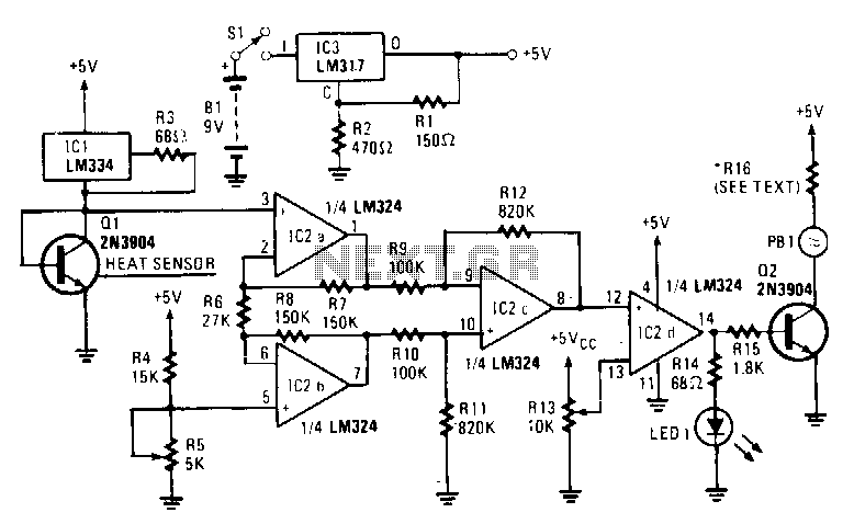
The sensing element Q1 is a 2N3904 general-purpose NPN transistor, although any general-purpose NPN unit in a TO-92 style case will suffice. IC1, an LM334, provides Q1 with a constant current that remains stable regardless of temperature variations. An...
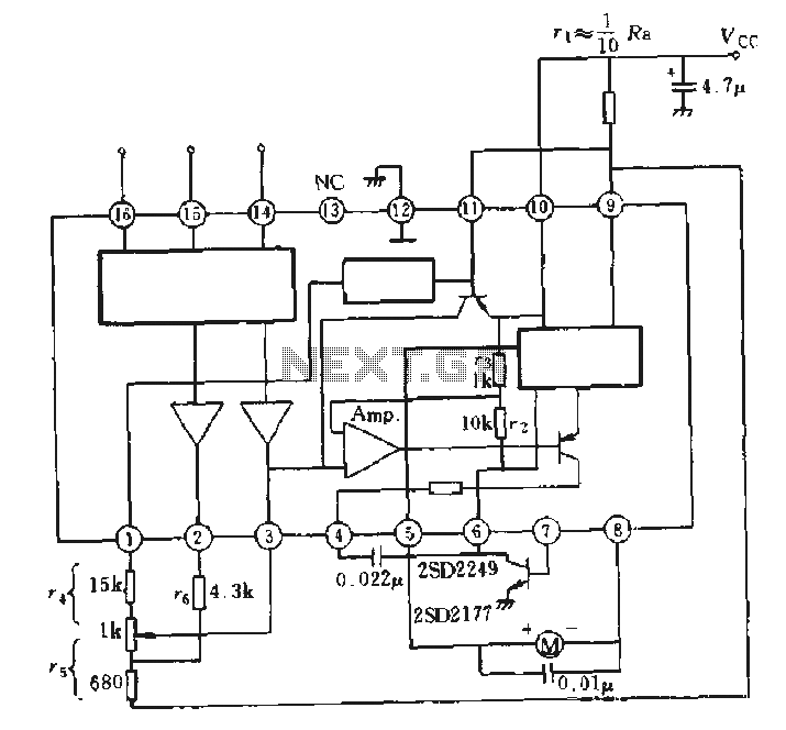
The AN6657 is a 16-pin dual in-line plastic package, while the AN6657S features a 16-pin dual flat plastic package. The speed control function operates with an internal H-bridge driver chip circuit, utilizing pins 5 and 8 for H-bridge driver...
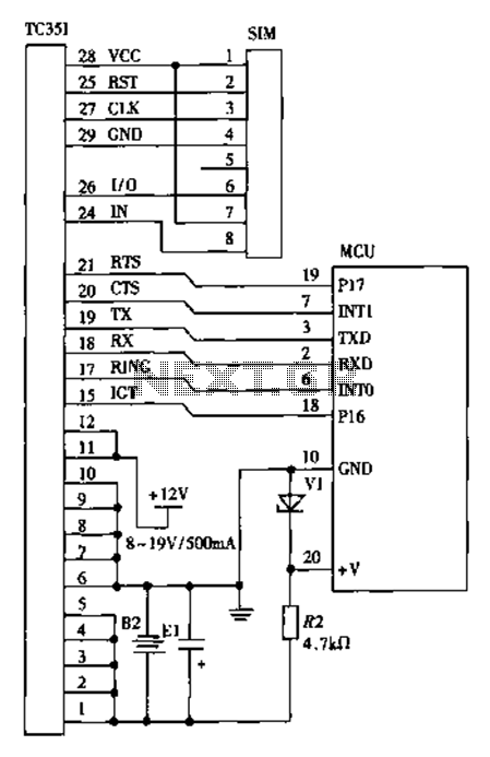
The design of a wireless data communication circuit is primarily intended for motor vehicles and fixed base station systems to facilitate close-range wireless data exchange. The circuit is based on the core chip nRF401 and its associated components. The...
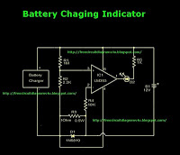
This is a battery charger indicator circuit diagram. When the battery is charging, it is indicated by an LED. This circuit can be used with a 12V battery with a charging current of less than 1A. The battery charger indicator...