
battery charger indicator circuit
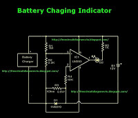
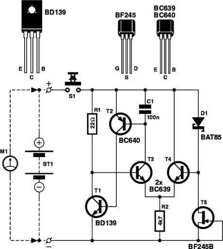
The battery charger indicator circuit is designed to provide a visual indication of the charging status of a 12V battery. It utilizes a light-emitting diode (LED) to signal when the battery is actively charging. The circuit operates with a charging current of less than 1A, making it suitable for various applications where low-power charging is required.
The primary components of the circuit include a resistor, a diode, and the LED itself. The resistor is used to limit the current flowing through the LED to prevent damage and ensure proper operation. The diode may be included to prevent reverse polarity, ensuring that the circuit functions correctly regardless of the battery's connection orientation.
When the battery is connected to the charger, and the charging process begins, current flows through the circuit. The LED will illuminate, providing a clear visual cue that the battery is charging. This feature is particularly useful in applications where the user may not be present to monitor the charging process continuously.
Additionally, the circuit can be integrated into various battery management systems or used as a standalone indicator for portable devices. Its simplicity and effectiveness make it a valuable addition to any battery charging setup, enhancing user awareness and safety during the charging process.This is battery charger indicator circuit diagram. When the battery charges it shows by the LED this circuit can be used with 12V battery with charging current less than 1A. 🔗 External reference
Related Circuits

This schematic represents a radio receiver circuit based on the TDA7088T, which is suitable for use in mono portable and pocket radios. The TDA7088T is a bipolar integrated circuit designed to operate with a minimal number of peripheral components...
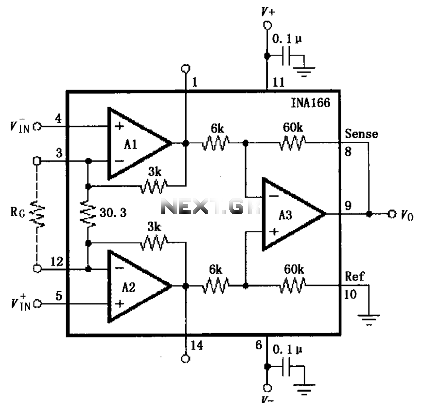
The basic connection circuit for the INA166 includes signal and power connections. A 0.1 µF tantalum capacitor should be used for filtering the chip's power supply terminal, and the PCB layout should be designed to position this capacitor as...
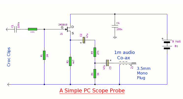
This simple PC scope probe functions as a FET follower, featuring high input impedance and low output impedance to match a microphone or line input socket on a PC or laptop. This design allows for practical examination of waveforms...
The primary function of the optical receiver is to extract information encoded on a modulated light carrier from a distant transmitter and restore it to its original form. A typical through-the-air communications receiver can be divided into five distinct...
Is the battery depleted, or is there an issue with the device? This question often arises when a battery-operated device, such as a Walkman, fails to power on. Before seeking professional repair services, it is advisable to first test...
Figure A illustrates the schematic of a microstrip single-stage RF amplifier. This amplifier utilizes the M/A-Com LF2810A MOSFET, which is rated for 10 watts and operates at 28 volts, but it delivers sufficient gain for this application at a...
Warning: include(partials/cookie-banner.php): Failed to open stream: Permission denied in /var/www/html/nextgr/view-circuit.php on line 713
Warning: include(): Failed opening 'partials/cookie-banner.php' for inclusion (include_path='.:/usr/share/php') in /var/www/html/nextgr/view-circuit.php on line 713