
A block diagram of AN6657 and basic application circuit
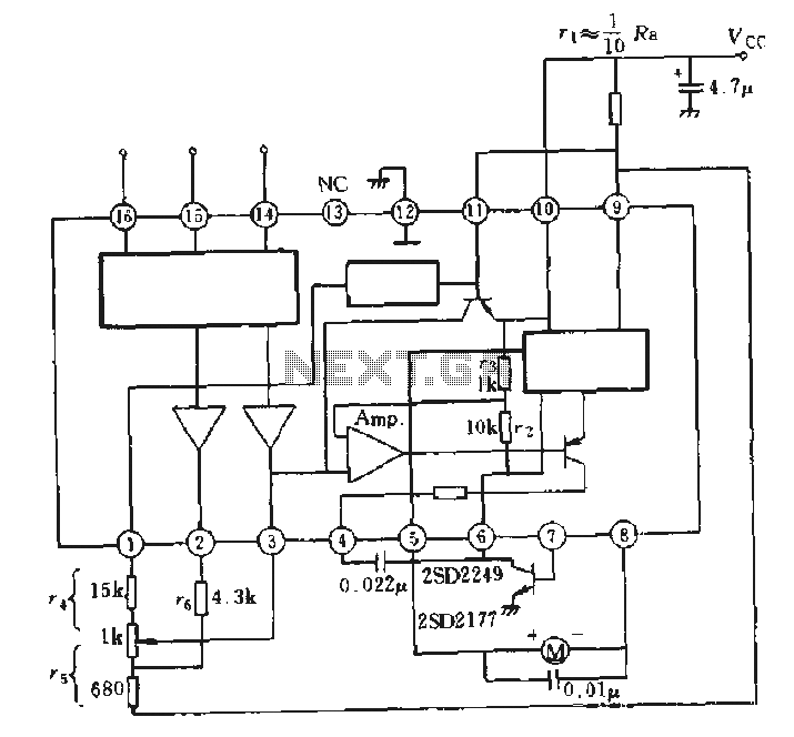
The AN6657 and AN6657S integrated circuits are designed for motor control applications, specifically for driving DC motors with bidirectional capability. The internal H-bridge configuration allows for efficient control of motor direction and speed by utilizing pulse width modulation (PWM) techniques. The device is capable of handling the required current levels to operate small to medium-sized motors, making it suitable for various applications, including robotics, automation systems, and consumer electronics.
In operation, the H-bridge driver outputs on pins 5 and 8 are responsible for controlling the polarity of the voltage applied to the motor terminals. When pin 5 is activated (set to a high logic level), current flows through the motor in one direction, causing it to rotate forward. Conversely, activating pin 8 reverses the polarity, allowing the motor to rotate in the opposite direction. The ability to control motor speed is achieved by modulating the duty cycle of the PWM signal applied to the enable pin, which is typically connected to an external control circuit.
The positive supply voltage for the H-bridge is provided through pins 9 and 11. This supply voltage must be stable and within the specified operating range to ensure reliable motor operation. Additionally, the external electrical contact resistance (R VCC) plays a crucial role in limiting the current and protecting the integrated circuit from overcurrent conditions.
Pin 6 serves as the connection point for the H-bridge arm, while the external NPN transistor connected to this pin is utilized to ground the circuit, enabling or disabling the motor operation based on the control signals. This configuration allows for enhanced control over the motor's behavior, including features such as braking and coasting.
Overall, the AN6657 series provides a compact and efficient solution for motor control applications, integrating essential features into a single package to simplify design and implementation.AN6657 is a 16-pin dual in-line plastic package, AN6657S 16-pin dual flat plastic package. 1. Speed Control works with internal H-bridge driver chip circuit, 5 and 8 feet H-bridge driver output, then charged motor. When 5 feet is positive, the motor is transferred; when 8 feet is positive, reverse the motor. H-bridge positive supply 9 and 11 feet, after an external electrical contact resistance r vcc. H bridge arm connected to 6 feet, after an external NPN transistor is grounded, see solid
Related Circuits
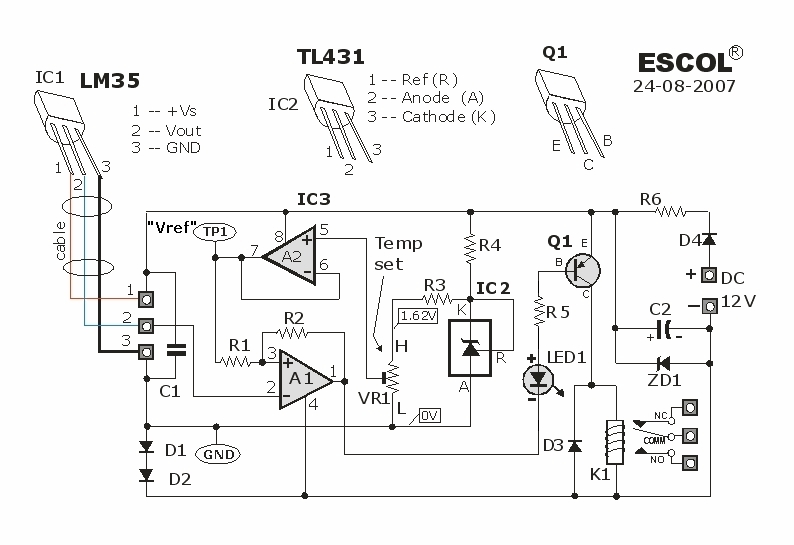
This temperature-controlled relay circuit is a simple yet highly accurate thermal control circuit that can be used in applications where automatic temperature regulation is required. The temperature-controlled relay circuit operates by monitoring the ambient temperature using a temperature sensor, such...
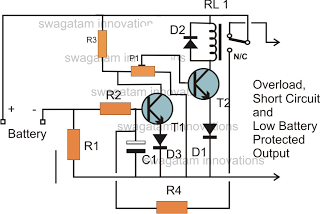
The battery voltage must pass through resistor R1 before reaching the output load. As a result, the current flowing through R1 is proportionately transformed into a voltage across it. When the battery voltage drops below a certain threshold, the...
The BTS412B functions as two high-side power MOSFET switches, while the BU271L components rated for 50V serve as the low-side switches. Together, these elements can form a bi-directional H-bridge DC motor drive circuit, as depicted in Figure 11-1l. This...
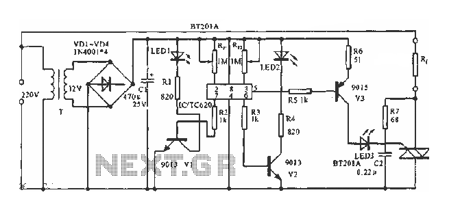
The circuit utilizes a built-in temperature sensor to control the triac TC620 for temperature regulation. The adjustment circuit consists of resistors Rp1 and Rn, which can be modified to set both the lower and upper temperature limits. LED1 illuminates...
It is based on an LM2917 and an SCR, which has the advantageous characteristic of preventing mis-timed sparks, a highly desirable feature for high-output rotary engines. When the engine reaches the rev limit during acceleration, the transition is smooth...
The bearing fault detector circuit consists of a bearing detection sensor, a signal processing circuit, a transistor (V), an audio amplifier integrated circuit (IC2), a speaker (BL), an RC element, an integrated circuit (IC1), and a light-emitting diode (VL)....
Warning: include(partials/cookie-banner.php): Failed to open stream: Permission denied in /var/www/html/nextgr/view-circuit.php on line 713
Warning: include(): Failed opening 'partials/cookie-banner.php' for inclusion (include_path='.:/usr/share/php') in /var/www/html/nextgr/view-circuit.php on line 713