
FLOW METER

The described circuit utilizes a Wheatstone bridge to measure resistance changes in the hot-wire anemometer. The bridge consists of four resistors, where R2 is the sensing element that responds to changes in fluid flow by changing its temperature and resistance. The overheat resistor R1 is strategically chosen to ensure that the circuit operates effectively within the desired temperature range. The op-amp amplifies the difference in voltage across the bridge, which indicates any imbalance caused by changes in the resistance of R2 due to varying flow conditions.
The feedback loop is crucial for maintaining the temperature of R2 at a constant level, which is essential for accurate flow measurements. The op-amp continuously adjusts the power supplied to the transistor based on the output of the Wheatstone bridge, ensuring that R2 remains at a temperature that is consistently higher than the surrounding environment. This feedback mechanism allows for precise control of the heating element, which is vital for the anemometer's functionality.
The construction of the hot-wire probe itself is also significant. Using Wollaston wire, known for its fine diameter and high resistance, enhances the sensitivity of the measurement. The wire's small mass allows for rapid thermal response, making it ideal for detecting minute changes in flow velocity. Proper insulation and mounting of the wire are critical to prevent heat loss and ensure accurate readings.
Overall, this op-amp and transistor circuit design provides a robust solution for fluid flow measurement, leveraging the principles of thermodynamics and electrical feedback to achieve high precision in various applications.Simple opamp circuit with one transistor gives reliable hot-wire anemometer for measuring flow of gases or liquids. R2 is heated above ambient temperature in Wheatstone bridge including overheat resistor R1which is calibrated to be 30% larger than cold resistance of R2.
Bridge is fed from power tran. sistor which is within feedback loop of opamp th at senses bridge unbalance. Output of bridge is fed back to power transistor in correct phase for maintaining constant- temperature condition in which R2 is approximately equal to R1. Article covers construction of hot-wire probe made from Wollaston wire. -W. Bank, Build Your Own Constant-Temperature Hot-Wire Anemometer, EDN Magazine, Aug. 1, 1972, p 43. 🔗 External reference
Related Circuits
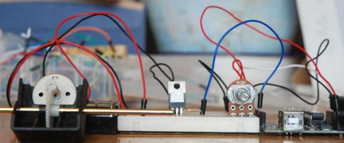
A quick circuit showing how to control the speed of a DC motor with a potentiometer with your Arduino board. Also shows how to use a TIP120 transistor to allow the Arduino control a larger power supply. This circuit utilizes...

Mains frequency is pretty stable and it is unlikely that you have to measure it but if you have an emergency generator you might find this circuit useful as it will give an indication whether the generator is running...

This is a simple application of the internal 10-bit ADC (analog-to-digital converter) of the PIC16F676 microcontroller. This circuit can be used to measure up to 30 V DC. Possible applications include a benchtop power supply or as a panel...

This temperature meter utilizes the precision micro power centigrade sensor IC LM35. The output voltage of the IC is linearly proportional to 10 mV per degree centigrade. The LM35 temperature sensor is a versatile and widely used device in electronic...

My circuit adds a transistor, to add feedback, and two resistors, to tailor the range of the control, with the result that a single-turn potentiometer gives a control range of about 2 to 30 microamps. I installed my circuit...

The circuit in Figure 1 is an RS-232/485 converter that uses the transmitted signal itself to control the flow. The circuit uses MAX232 and MAX483 interface circuits, IC1 and IC2 from Maxim Integrated Products to convert between the ICs'...