
Control the speed of a DC motor with a potentiometer with an Arduino board
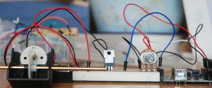
This circuit utilizes an Arduino microcontroller to adjust the speed of a DC motor through a potentiometer. The potentiometer acts as a variable resistor, allowing the user to change the voltage signal sent to the Arduino. The Arduino processes this input and adjusts the output signal accordingly.
The TIP120 transistor is employed as a switch to control the larger power supply required by the DC motor. When the Arduino sends a PWM (Pulse Width Modulation) signal to the base of the TIP120, it allows current to flow from the collector to the emitter, powering the motor. The TIP120 can handle higher currents, making it suitable for driving motors that require more power than the Arduino can supply directly.
The circuit typically includes the following components:
1. Arduino Board: The microcontroller that processes input from the potentiometer and controls the TIP120.
2. Potentiometer: A variable resistor that allows the user to set the desired motor speed.
3. TIP120 Transistor: A Darlington pair transistor used to switch the motor on and off and control its speed.
4. DC Motor: The load that is being controlled, which varies its speed based on the potentiometer setting.
5. Diode: A flyback diode is often included across the motor terminals to protect the circuit from voltage spikes generated when the motor is turned off.
6. Power Supply: A separate power source that provides the necessary voltage and current to drive the motor.
The connections are made as follows:
- The potentiometer is connected to one of the analog input pins on the Arduino, with its other terminals connected to ground and the 5V supply.
- The base of the TIP120 is connected to a PWM-capable digital output pin on the Arduino through a current-limiting resistor.
- The collector of the TIP120 is connected to one terminal of the DC motor, while the other terminal is connected to the positive side of the external power supply.
- The emitter of the TIP120 is connected to ground.
- The flyback diode is placed in parallel with the motor terminals, oriented to allow current to flow back to the power supply when the motor is turned off.
This setup allows for smooth control of the motor speed, providing an effective solution for various applications requiring variable speed control.A quick circuit showing how to control the speed of a DC motor with a potentiometer with your Arduino board. Also shows how to use a TIP120 transistor to allow the Arduino control a larger power supply. 🔗 External reference
Related Circuits
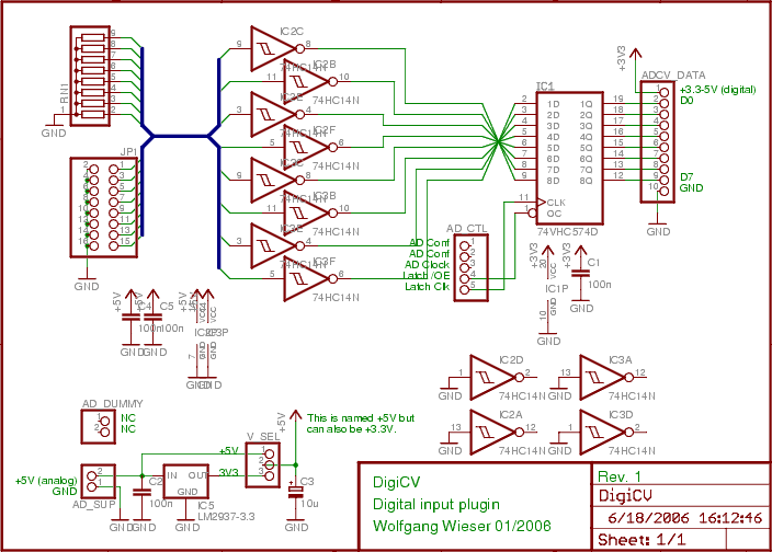
The digital input board features eight distinct digital inputs available on connector JP1. Each input is equipped with separate pull-down resistors (RN1, with a recommended value of 1 MΩ) and a Schmitt-trigger. To prevent damage from improper input voltages,...
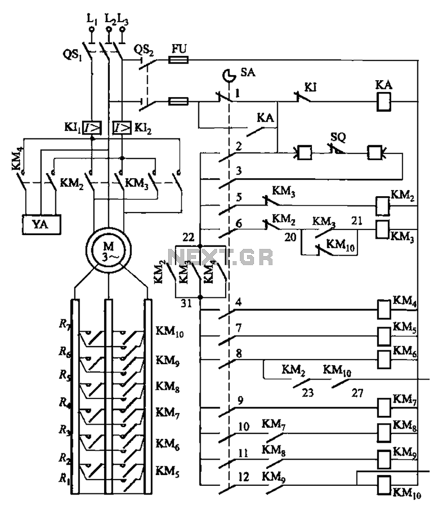
The system is managed by the master controller LKl-12/90 and a magnetic disk control unit PQR10A, which includes a control circuit. The cam control device SA is responsible for contact closure, as indicated in Table 8-5. The main electrical...
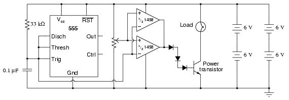
This circuit utilizes a 555 timer to generate a sawtooth voltage waveform across a capacitor, which is then compared to a steady voltage provided by a potentiometer using an operational amplifier (op-amp) configured as a comparator. The comparison of...
The primary concept is to rotate the motor slightly every 15 seconds. A monofilament line conveys the motion to the ornament, which is wound by the motor and gradually unwinds as the ornament turns. The charging circuit includes a...

This is a circuit for Closed-Loop Automatic Power Control for RF Applications. The circuit utilizes a log detector (AD8318) and a variable gain amplifier (VGA) (ADL5330). The Closed-Loop Automatic Power Control (APC) circuit is designed to maintain a consistent output...
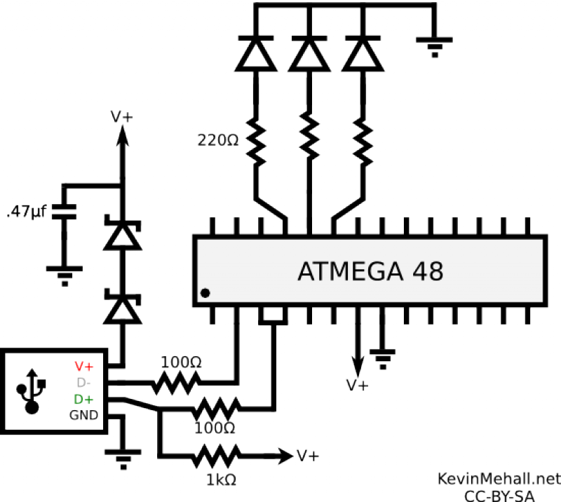
The article on the RGB LED fader has been one of the most visited articles on this blog. Since its publication, another microcontroller-based RGB LED project has been designed and built, this time controlling the colors from a computer...
Warning: include(partials/cookie-banner.php): Failed to open stream: Permission denied in /var/www/html/nextgr/view-circuit.php on line 713
Warning: include(): Failed opening 'partials/cookie-banner.php' for inclusion (include_path='.:/usr/share/php') in /var/www/html/nextgr/view-circuit.php on line 713