
Fluorescent Lamp Driver Circuit and Project
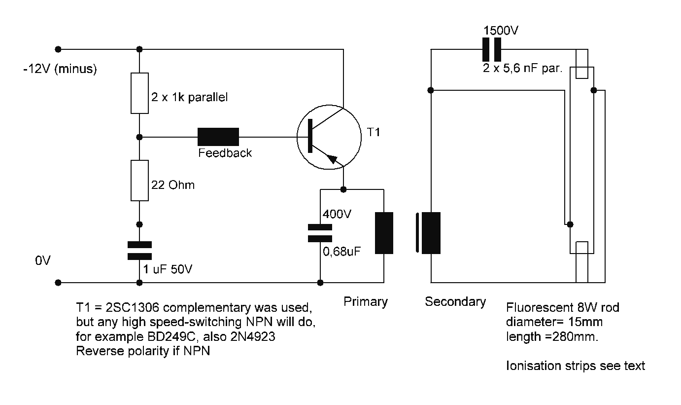
Fluorescent lamps require a specific starting voltage to ionize the gas within the tube and initiate the lighting process. In inverter applications, particularly those utilizing 12V systems, the challenge lies in providing sufficient starting voltage while maintaining energy efficiency.
An inverter circuit designed for fluorescent lamps typically includes several essential components: a DC-DC converter, a high-frequency oscillator, and a transformer. The DC-DC converter steps up the 12V input to a higher voltage necessary for starting the lamp, often reaching levels around 400V to 600V. The high-frequency oscillator generates a pulse-width modulated (PWM) signal that drives the transformer, allowing for efficient energy transfer and higher output voltage.
The transformer used in this application is crucial; it must be designed to handle the high-frequency operation and provide isolation between the high-voltage output and the low-voltage input. Additionally, the design may include feedback mechanisms to regulate the output voltage and current, ensuring stable operation as the lamp warms up and reaches its steady state.
To enhance efficiency, the inverter may incorporate features such as soft-start circuits, which gradually increase the voltage applied to the lamp, reducing stress on the lamp and extending its lifespan. Furthermore, the circuit may include protective components like fuses or circuit breakers to prevent damage from overcurrent conditions during startup.
In summary, designing a 12V driver for fluorescent lamps on an inverter involves careful consideration of voltage requirements, component selection, and efficiency optimization to ensure reliable operation and longevity of the lamp.Starting a fluorescent on an inverter The 12V drivers for fluorescent lamps are tricky, because of the compromise between a good operating efficiency 🔗 External reference
Related Circuits

This 200-watt audio amplifier circuit diagram is based on the STK4050V high-power audio amplifier IC, designed to deliver up to 200 watts of audio power on a single channel. The STK4050V 200-watt audio amplifier circuit is pin-compatible with other...
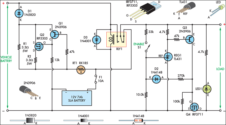
The SLA battery is charged from the vehicle's battery. When the engine is running, the voltage remains fairly constant, which greatly simplifies the charging circuit. If the SLA battery is fully charged, any further charging current from the vehicle...
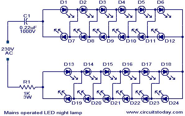
A simple and effective LED-based night lamp circuit is designed to operate directly from the 230V mains supply. The circuit utilizes a total of 24 white LEDs, producing an output of approximately 15W. Current limiting is achieved through resistor...

The work process analysis circuit diagram illustrates the use of a flyback converter transformer model. The flyback transformer primarily consists of ideal transformer magnetizing inductance and leakage inductance components. The flyback converter circuit exhibits high-frequency resonance at both ends...

With switch SI in the off position, battery voltage is applied across timing capacitor CI, which remains charged while the rest of the circuitry is powered off. Transistor Q1, and consequently transistors Q2 through Q4, remain in an off...
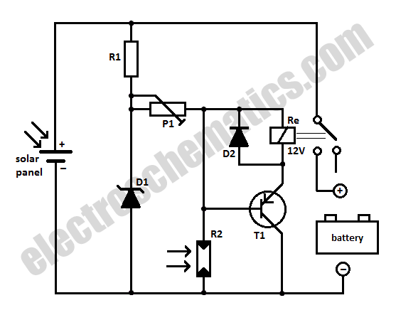
When charging a battery during the day using a solar panel, there is a risk of the battery partially discharging through the panel after sunset. This solar panel power switch circuit eliminates the need for a diode by utilizing...