
Mains operated LED night lamp
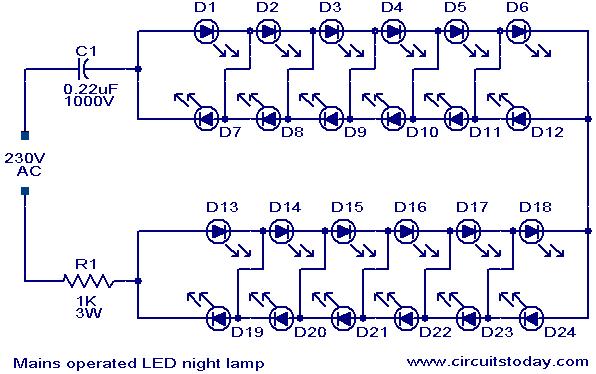
The circuit operates by connecting a series of LEDs in a configuration that allows them to be powered from the mains supply. The use of R1 and C1 ensures that the current flowing through the LEDs remains within safe limits, preventing damage. Additionally, the circuit is designed to handle voltage fluctuations, enhancing its reliability.
In troubleshooting scenarios, if the LEDs do not illuminate after initial operation, it may indicate a fault in the components. For example, connecting a capacitor in series with the LED pairs can help determine if the issue lies with the LEDs. The LEDs are typically rated for 3.2 volts and 15mA, and if they fail to light up, a thorough inspection is necessary.
It is essential to verify the specifications of the components used, particularly the capacitors and resistors, to ensure they meet the circuit's requirements. For instance, using capacitors rated for higher voltages can prevent potential failures. In cases where the circuit shows faint glowing after being switched off, it may be due to leakage paths in the circuit, which can be mitigated by adding a resistor in parallel with the capacitor to facilitate quicker discharge.
When using different sizes or types of LEDs, adjustments to the values of R1 and C1 may be necessary to accommodate the specific voltage and current requirements. For example, using 3mm LEDs may require a modification of the capacitor value to 0.33uF and reducing R1 to 220 ohms to achieve optimal performance.
In summary, this LED night lamp circuit combines simplicity and functionality, with careful consideration of component selection and circuit design to ensure reliability and performance. Proper assembly and testing are crucial for successful operation, and adjustments may be needed based on the specific LEDs used in the project.Here is a simple and powerful LED based night lamp circuit that can be operated directly from the 230V mains supply. The are total 24 white LEDs used and the lamp produces an output of around 15W. The resistance R1 and capacitor C1 provides necessary current limiting. The circuit is sufficiently immune against voltage spikes and surges. Hi Jay may be your capacitor is faulty. connect 0. 25 in series with one pair of LED back to back and with 1k 1 watt also inseries and try for the glow. if nothing happens and if the LEDs glow OK. then the fault is that the LEDs are rated for 3. 2volt 15mA. Hello Seetharaman, What could be the cause why all the LEDs got busted It was working for some 15 seconds but it did not glow anymore after I have switched it off then on again.
Hello Seetharaman, I have checked the LEDs with lithium cell. Unfortunately, all 6 LEDs are dead. Yes, I have actually used two capacitors (0. 25 & 0. 1uF) both at 630v in parallel. I hope that the voltage is not too much if its in parallel I am not sure if the caps are still working after the test that I have made . Jeh Hi Jeh one of yur LED might have blown. With a magnifying glass look into LED if any block spot is seen it is blown. you can check each LED`s glow by using a lithium 3 volt disc cell-faster method. Is your 0. 35uF rated for 400 volt. Hello Seetharaman, I was able to assemble the project. Fortunately it was working when I plugged it for 15seconds however, when I switched it off then turned it on after some seconds the LEDs did not glow anymore till now.
What do you think is the error I have used 0. 35uF Capacitor and 220ohms 1 watt resistor. There is no sign of burn or any part that gets hot. Thank you, Jeh Hi Jeh it will be 5mm 3volt @ 20mA variety. So my earlier comment of 8th june is ok for your application. Normally 7. 5mm will come as jewel lamp with 2 leads for panel indication use. please donot worry about it. You go ahead thinking as 5mm ( some makes are around 5. 5mm with 2 leads one little longer, indicating anode) Dear Seetharman, I was the one who measured it actually and it is more than 5mm but less than 10mm. The store told me that it is 3volts. It has two leg terminals, cylindrical with almost flat top part. It looks the same as the 3mm size LED. Well, I just dont know if it falls to the 5mm size category. I can send you a photo to your email if you could send me yours. Hi Jeh as per the voltage and current requirement of the LEDs the values of C1 and R1 will change. Send me the details of your 7. 5mm LED, it is not a standard size. (normally freely available in the market sizes are 3, 5, 10 mm) Hi Jeh 3 volt 3mm white LEDs will consume 20mA at 3.
6 volts. 3Pairs back to back. Increase C1 to 0. 33uF. no other modifications are required. The power consumption will be around 3/4 watts for the modified circuit. By reducing R1 to 220 ohms your consumption will be less than 0. 4watts. Hello Seetharaman, using the same circuit but using only 6pcs 3volts 3mm diameter LEDs, can you help me if what values of capacitor and resistor should I use I was able to complete the first project but the store run out of LED. the charge available in the capacitor is getting completed through the leakage path in your holder circuit and you will have faint glow for a long time.
then it will become dark. to avoid this problem add a 100K 1/4 resistance in parallel with C1 which will discharge the capacitor fast hence the glow LEDs will fade away fast. Thanks Seetharaman for the reply. Just a small clarification, when you say back to back you mean I will connect the two LEDs with one +leg of 1 LED to the -leg of the other LED and vice-versa By the way the circuit is a great one!
Congratulations for that! I just dont know if it is normal that when I switch it off some LEDs are a bit glowing and they don`t go off unless I remove totally the unit from the mains Maybe you could help me again to solve thi 🔗 External reference
Related Circuits
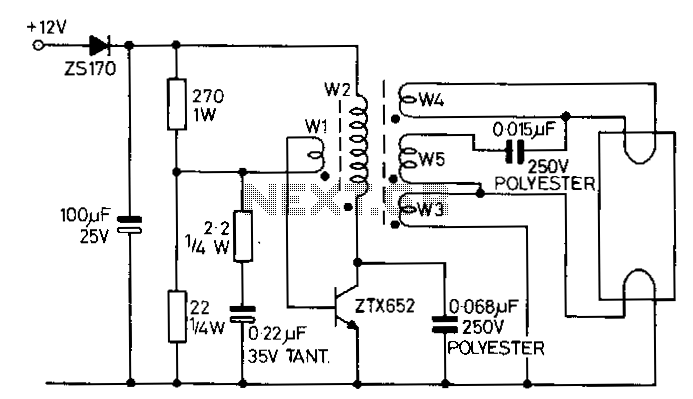
This circuit is designed to drive an 8-W fluorescent lamp from a 12-V power source using a cost-effective inverter based on the ZTX652 transistor. The inverter operates with supply voltages ranging from 10 to 16.5 V, making it suitable...
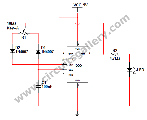
How to change the brightness of an LED. Are LED lights dimmable? Is it possible to adjust the brightness of LEDs? An LED is essentially a diode; when the forward voltage exceeds 0.7 volts, it begins to emit light,...
This battery allows the indicator to the car battery voltage monitor. The indicator has four LEDs which indicate power. The more LEDs, the higher the voltage. The last LED is a flashing LED. It comes on when the accuspaning...
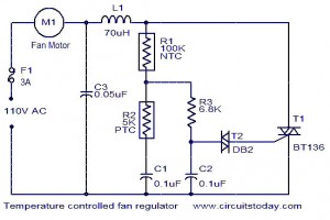
The function for automatically controlling the speed of a fan according to the temperature. Components: BT136 Triac, Capacitor, Resistor, Relay, Fan Motor. This circuit is designed to automatically adjust the speed of a fan based on the ambient temperature. It...
A 0 to 2 MHz frequency meter with a Minimum Mass Wireless Coupler, based on the ATMega8. Range to the Minimum Mass Base Unit is 10 to 15 cm. Since the frequency meter is battery operated, it can be...
Feedback in a public address amplifier should be avoided. The ideal solution is to adjust the positions of the microphone and speaker; however, this is not always feasible in many situations. A frequency shifter that alters the output frequency...
Warning: include(partials/cookie-banner.php): Failed to open stream: Permission denied in /var/www/html/nextgr/view-circuit.php on line 713
Warning: include(): Failed opening 'partials/cookie-banner.php' for inclusion (include_path='.:/usr/share/php') in /var/www/html/nextgr/view-circuit.php on line 713