
In-Car Charger And Switcher Circuit For SLA Battery circuit

The circuit operates by utilizing the vehicle's battery to charge a sealed lead-acid (SLA) battery while the engine is running. The design leverages the relatively stable voltage output of the vehicle's alternator, which simplifies the charging process. The charging circuit includes a resistor (R1) rated at 3.3W to 5W, which serves to limit the charging current when the SLA battery reaches its full charge. This resistor prevents overcharging and protects the battery from damage due to excessive current.
In scenarios where the SLA battery is deeply discharged, the voltage drop across resistor R1 becomes significant enough to activate the base of the PNP transistor Q1. This activation leads to the conduction of Q1, which in turn triggers the P-channel MOSFET Q2. The MOSFET then allows additional charging current to flow through a secondary resistor (R2) connected in series. This configuration effectively creates a two-step charging system, where the initial charging phase is controlled by R1 and the secondary phase is managed by the MOSFET and R2.
The two-step charging approach is beneficial as it allows for a more controlled and efficient charging process, reducing the risk of battery damage and extending the overall life of the SLA battery. The design is particularly useful in automotive applications, where maintaining battery health is crucial for reliability and performance. The circuit's simplicity and effectiveness make it an ideal solution for integrating SLA batteries into vehicle electrical systems.The SLA battery is charged from the vehicle s battery. When the engine is running, the voltage remains fairly constant, which greatly simplifies the charging circuit. If the SLA battery is fully charged, any further charging current from the vehicle battery is limited by a 3.3W 5W resistor (R1).
If the SLA battery is deeply discharged, the voltage drop across this resistor will be enough to bias on PNP transistor Q1. This will turn on P-channel Mosfet Q2 and it will provide further charging current via R2, effectively becoming a 2-step charger..
🔗 External reference
Related Circuits
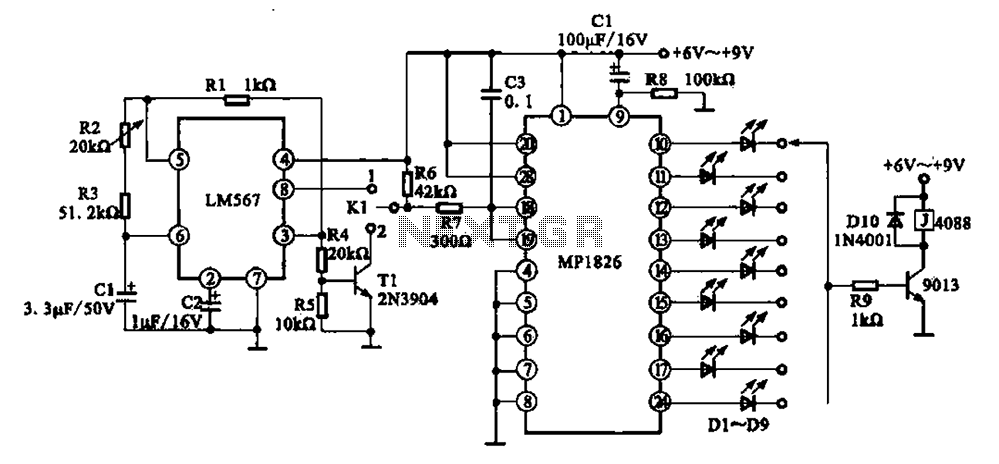
A precision circuit utilizing the LM567 timer, specifically the MPI826, where the LM567 functions as a dual-band oscillator. The MP1826 serves as a divider in the circuit, allowing the output signal from the LM567 to achieve extended timing. The...
The circuit under discussion is a four-siren sound generator utilizing the UM3561 integrated circuit (IC), which is a low-power CMOS device. Four distinct sounds can be generated by activating switches S1, S2, and S3. This circuit is versatile and...
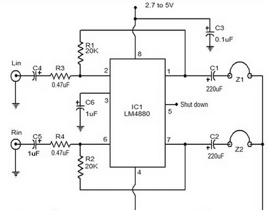
The LM4880 is a dual audio HiFi amplifier integrated circuit from National Semiconductor. This headphone amplifier circuit is specifically designed to produce high-quality audio output with a minimal number of components. The LM4880 integrated circuit is capable of delivering...
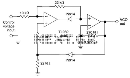
This circuit utilizes the AD639 universal trigonometric function generator from Analog Devices to transform a triangle waveform, which serves as the fundamental waveform of the VCO, into a low-distortion sine wave. By operating the AD639 in its frequency tripler...
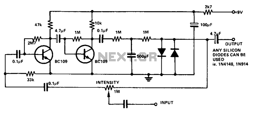
The circuit utilizes a transistor to amplify the input signal. Two diodes are employed to clamp the distorted output, while a 500 pF capacitor filters out high-frequency noise. Under normal conditions, a 1M slide rheostat is used to adjust...
A solar cell radio utilizes a 3V power supply, which can be provided by either a single 3V battery or two 1.2V Ni-Cad batteries connected in series. The battery is non-removable, and the device features a mini jack socket...