
Fluorescent Tube Basics Schematic Diagram

The fluorescent lamp operates through a series of interconnected components that work in unison to produce light efficiently. The key components include the fluorescent tube, starter, ballast, and power factor correction capacitor. The fluorescent tube is filled with a low-pressure gas mixture, primarily mercury vapor, and coated with phosphorescent materials on the interior surface. When an electrical current is introduced, the starter ignites the gas, enabling the arc to form and produce ultraviolet light. The ballast regulates the current flowing through the lamp, preventing damage from excessive current while ensuring the arc remains stable.
The starter plays a crucial role in initiating the lamp's operation. The bimetallic strip within the starter acts as a switch, momentarily allowing current to flow through the filaments, which heats them up to the necessary temperature for sustaining the arc. Once the arc is established, the starter's function is no longer needed, and it becomes inactive.
The ballast's design is critical, as it must provide the necessary inductance to limit the current while minimizing power losses. This is often achieved through the use of copper wire, which, while efficient, does introduce some resistance. The balance between inductive and capacitive reactance is essential for maintaining an optimal power factor, which is particularly important in larger installations where energy efficiency is a priority.
In summary, fluorescent lamps are complex devices that rely on a combination of gas chemistry, electrical components, and circuit design principles to function effectively. Understanding these interactions provides insight into their operation and the importance of each component in achieving efficient lighting solutions.While they have been with us for many years, fluorescent lamps remain somewhat mysterious to most people. This isn`t really surprising, since their operation isn`t simple. The tube itself contains a mixture of gases, but the active ingredient is mercury. When operated as an arc, mercury vapour emits a vast amount of short-wave ultraviolet light. T his is invisible, but phosphors on the inside of the tube itself fluoresce when struck by UV, and are designed to emit visible light. Most of the remaining UV light is absorbed by the glass, which is opaque to ultraviolet (this is why you can`t get a suntan from behind a glass window).
Refer to Figure 1 to follow the explanation. This also shows a representation of the fitting that was used for the illumination tests. For all tests, only the centre tube was installed, with the others removed to ensure that each lamp was operating under near identical conditions. In order to start the arc inside the tube, a starter is used. This is a small neon lamp, with a bimetallic strip contact mechanism built in. When power is first applied, the neon conducts a small current - enough to heat the bimetallic strip, and this causes the switch to close.
Once closed, current flows through the filaments at each end of the tube via the ballast, bringing them to working temperature. The ballast limits the current to a safe value. The filaments themselves are fairly rugged, and are typically around 2 Ohms resistance each. While the switch in the starter is closed, there is no current flow through the neon gas in the starter.
The bimetal strip cools and the contacts open. When current drawn through an inductor is suddenly interrupted, a high voltage is generated as the magnetic field collapses. This high voltage will (hopefully) strike the arc in the tube. As most people will have noticed, fluoros usually flicker a few times when turned on. This is usually because the initial strike is insufficient to maintain the arc because the gas temperature is too low.
After a few strikes, the temperature is high enough that the arc maintains itself. Maximum light output is usually not achieved for around 5 minutes, but the difference is not very noticeable with tubes in reasonably good condition. Once the arc is struck (and maintained), the ballast has a new task. An arc has negative resistance, so as the voltage across the tube falls, the current increases. The ballast limits the current to a safe value, as determined by the tube`s ratings. With a continuous arc, the voltage across the tube is too low to allow the neon gas in the starter to conduct, so the starter is effectively bypassed.
Old tubes will often be unable to maintain an arc, and this is why they flash and flicker, with the starter constantly opening and closing because the arc is not self-sustaining. Since AC is applied to the tube, the arc actually stops and re-strikes on each half cycle, causing the light to flicker at 100 (or 120) Hz.
This is normally not visible, but a tube at the end of its life may only conduct fully in one direction. This causes a 50/60Hz flicker that is often visible and annoying to some people. Because the ballast is an inductor, it should dissipate no power, but this can never be the case in reality.
Inductors are wound with copper wire, which has resistance. If nice thick wire were used, this resistance could be minimised, but to do so is very expensive. A compromise is reached where ballast losses are deemed "reasonable", and cause the temperature rise due to power loss to remain within allowable limits. New regulations will soon specify the maximum allowable power loss in ballasts, which will see a return to larger (and more expensive) types than we commonly see today.
Finally, a capacitor is (or should be) installed in parallel with the incoming mains. This is sized to suit the ballast inductance and supply frequency. The capacitive reactance of the PFC (Power Factor Correction) cap should exactly balance out the inductive reactance of the ballast. If this is done properly, the power factor will be 1 - a perfect result. This cannot happen with a fluorescent lamp though, because the current drawn is not linear. The voltage across the tube is a reasonable approximation to a squarewave because of the arc characteristics, and the maximum achievable power factor is normally around 0.
9 (90%). Typical fittings manage 0. 85 or so (some are better than others). This means that the current drawn from the mains will be 10% higher than necessary to produce the lamp`s rated power. This means that for a 36W fluorescent lamp, the minimum attainable current will be around 190mA at 230V because of ballast losses.
The ideal current (if power factor correction were perfect) would be 174mA, allowing for a total typical load of 40W. For many commercial and industrial installations, the `lead-lag` circuit shown above is common. By including the power factor correction cap in series with one of the ballasts, the power factor is brought to around 0.
85 as with the approach shown above, but the capacitor is smaller and thus cheaper than would be the case if the ballasts were in parallel. Note that where 120V (60Hz) mains voltages are used, you may find that ballast is actually an auto-transformer.
This is used because the voltage is not quite high enough to ensure reliable operation, and the auto-transformer configuration boosts the voltage. Figures 1 and 1A are for fittings operating from 220-230V, which need no voltage boost for normal operation.
Predictably, the circuits for auto-transformer ballasts are different from those shown here, but similar techniques are used. 🔗 External reference
Related Circuits
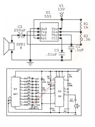
An astable oscillator is constructed using a 555 timer, producing an alarm tone of 1.8 kHz that directly drives a speaker. This fundamental alarm circuit serves as a basis for various other projects in the book. Although the circuit...
Nearly all AM radio manufacturers utilized this specific circuit from approximately 1948 to 1963. There is a growing interest in collecting these radios as antiques. Credit for the creator of this figure and caption is sought, but the source...
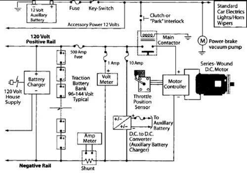
After charging the batteries for many hours with the 12V charger and PowerCheqs, a drive of about 5 miles resulted in the low battery light activating. The PakTrakr indicated that the battery adjacent to the most positive battery required...
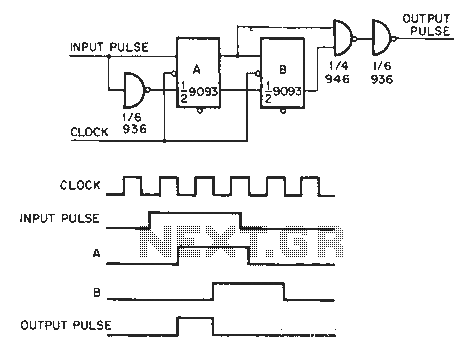
The circuit generates a clock that is synchronized with the pulse width of two clock pulses, producing a random pulse width that is five times the input pulse width of the clock pulse. In the flip-flop circuit, A and...
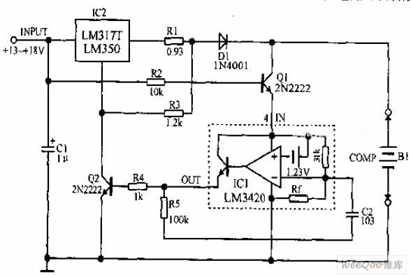
A lithium-ion battery charging circuit is illustrated above. Initially, when charging begins, if the battery voltage is below 8.4V, the output of IC1 is inactive. As a result, Q2 remains off, and the LM317 operates in constant current mode....
Pure Class-A triode OTL design and only one tube for amplification. The plate voltages should be low. The output impedance should be as low as possible and the maximum output current should be as high as possible. This amplifier...