
5 Tube AC/DC Radio Receiver

The AM radio circuit in question is characterized by its simplicity and effectiveness, which contributed to its widespread adoption during the stated period. The circuit typically includes essential components such as a power supply, an oscillator, a modulator, a detector, and an audio amplifier.
The power supply provides the necessary voltage levels for the operation of the circuit, while the oscillator generates the radio frequency (RF) signal that carries the audio information. The modulator combines the audio input with the RF signal, allowing the audio to be transmitted over the airwaves.
The detector, often a diode, demodulates the received RF signal, extracting the audio signal for further amplification. Finally, the audio amplifier boosts the audio signal to a level suitable for driving speakers, enabling sound reproduction.
This circuit design is notable for its robustness and ability to operate effectively in various conditions, contributing to the popularity of AM radios during the mid-20th century. The simplicity of the design also facilitated manufacturing, making these radios accessible to a broader audience. As a result, many collectors today seek out these vintage models, appreciating their historical significance and the nostalgia they evoke.Virtually all AM radio manufacturers used this exact circuit from about 1948 to 1963 or so. People are starting to collect these radios as antiques of sorts. I would be happy to credit the creator of this figure and caption, but I don`t recall from where I down-loaded this. If you made it or know who did, please give me an electronic holler. 🔗 External reference
Related Circuits

A schematic of the ability accumulation is presented below. Similar to the amplifier schematic, the ability accumulation design is © OddWatt Audio, and permission to host the schematic on this platform has been granted by OddWatt Audio. The schematic...
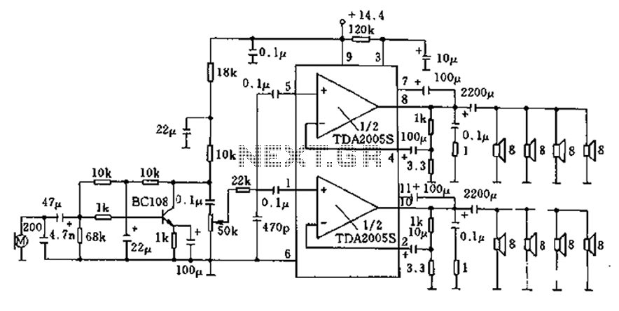
20W bus radio and megaphone circuit utilizing the TDA2005S double low-frequency power amplifier integrated circuit design. The front end can be connected to either a microphone input or a low-frequency radio output voltage amplification stage. Each TDA2005S provides 10W...
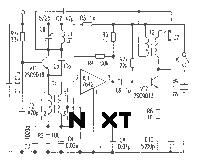
This article discusses the functionality of a super-regenerative FM receiver. The principle behind this receiver utilizes high-gain miniature integrated circuits, resulting in a simple and innovative circuit design. It achieves the performance level of standard FM receivers while addressing...
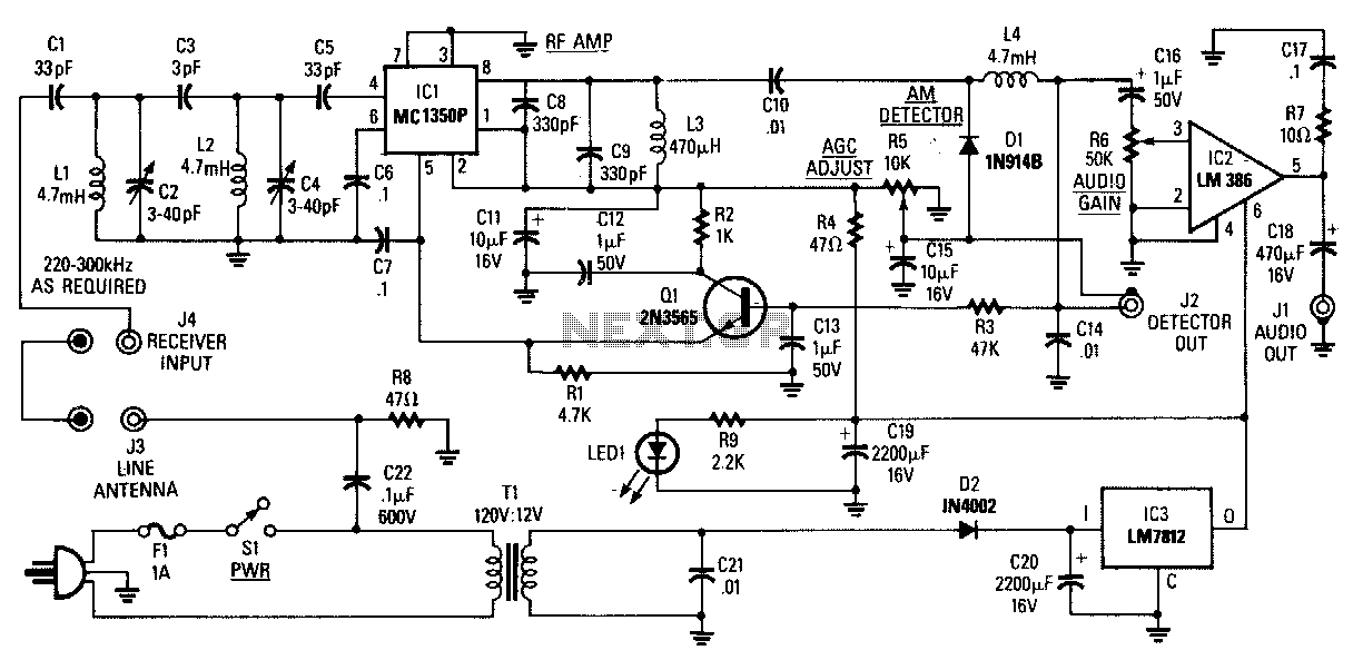
The AM Tuned Radio Frequency (TRF) receiver has a sensitivity of approximately 1 mV at the input for an audio output of 1/2 W. Capacitor C22 couples audio signals from the power line to the PC board and must...
The driver stage operates similarly to the previously described class A output stage, but it functions at a few milliamps, making efficiency less of a concern. The biasing configuration should be recognizable. Some circuits, including the one mentioned, incorporate...
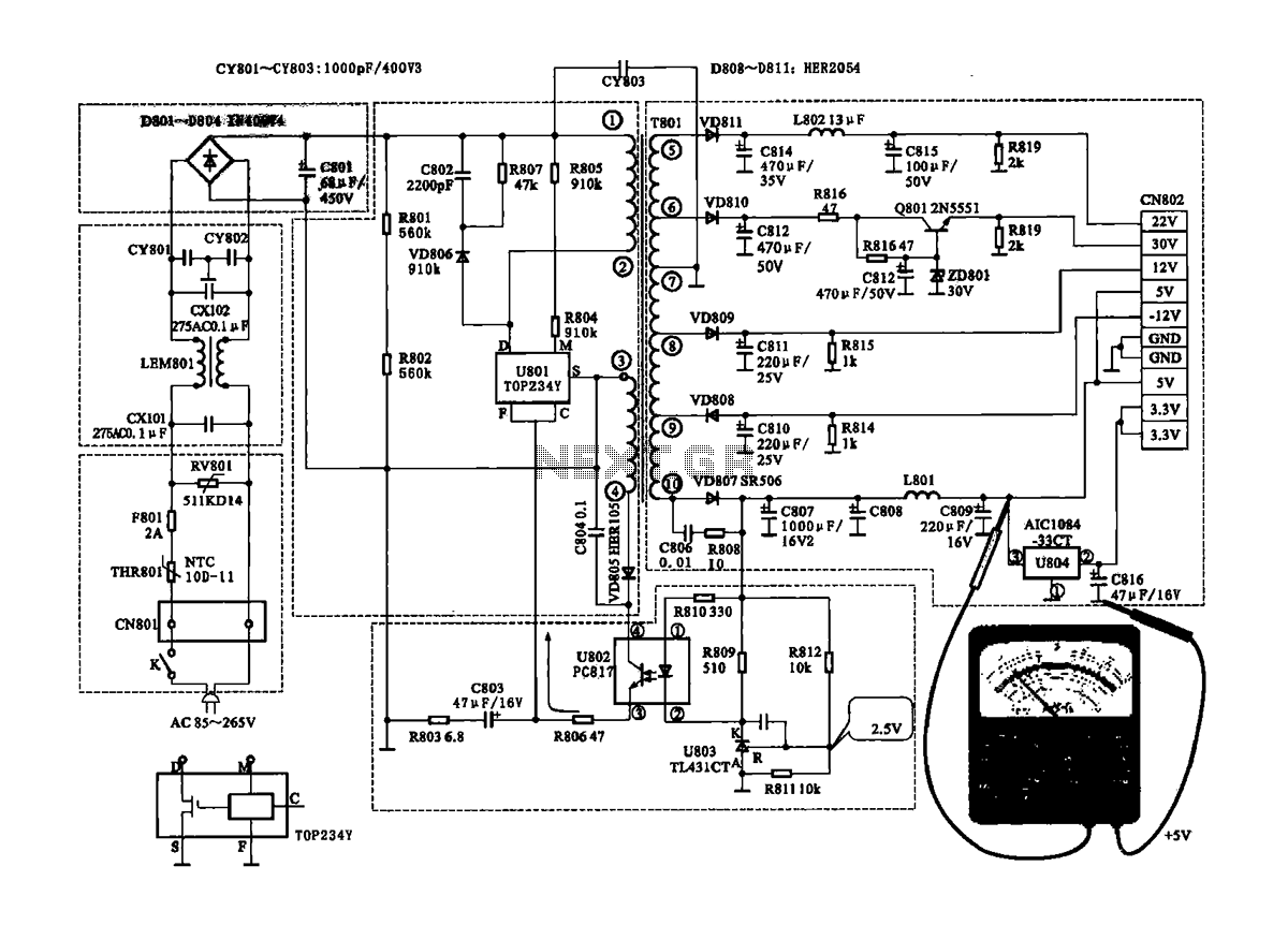
The Coship CDVB3188V receiver features a switching power supply circuit similar to the CDVB3188C model. The circuit includes several key components: an AC input circuit, an anti-jamming filter circuit, a complete flow filter circuit, and a switching oscillation circuit....