
Fly auto disinfestation effect circuit
The electronic fly disinfestation system employs a straightforward yet effective design that integrates various electronic components to achieve its purpose. The relaxation oscillator, composed of resistors and capacitors, is critical for generating the pulse signals necessary for the thyristor's operation. The thyristor acts as a switch that controls the high-voltage discharge, which is pivotal for electrocuting the flies. The transformer plays a vital role in stepping up the voltage to the required level for effective fly disinfestation.
The high-voltage grid, strategically designed with equidistant metal filaments, ensures that flies landing on the bait are effectively electrocuted, thus preventing them from escaping. The design considerations, such as the choice of components, spacing of the grid wires, and the sealing of the fly box, are essential for maximizing the system's effectiveness while ensuring safety. The dimensions and construction materials of the fly box are tailored to provide a compact yet functional unit that can be easily deployed in various environments.
The operational frequency of the system, adjustable through the resistor R3, allows for optimization based on specific environmental conditions, contributing to the overall efficiency of the device. The use of a tantalum capacitor for C1 is particularly important as it ensures reliable performance by minimizing the risk of leakage, which could otherwise compromise the system's functionality. The assembly and drying process of the transformer are also critical steps that enhance the durability and reliability of the high-voltage output.
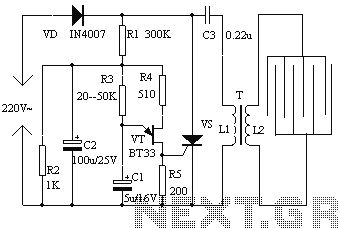
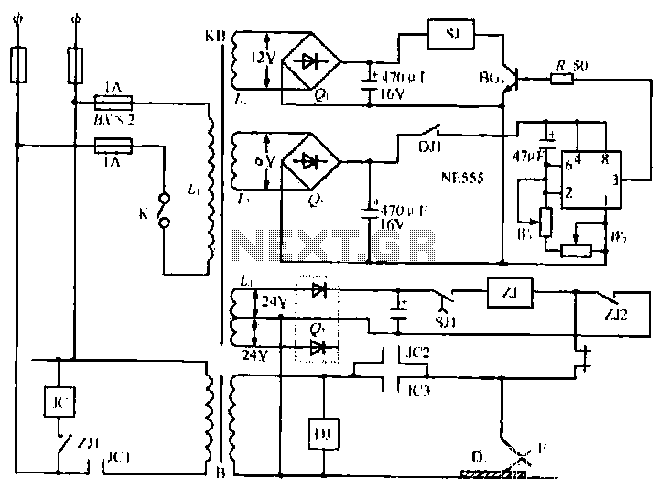
In summary, this electronic fly disinfestation system combines effective engineering principles and electronic components to provide a reliable solution for fly control, making it suitable for various applications in both residential and commercial settings.The electronic fly disinfestation simple and easy system for all electrical fly online, you can wipe out. The apparatus shown in Figure 1 circuit. The entire device consists of 220V mains powered directly by the rectifier. R3, R4, R5, C1 and double base diode relaxation oscillator, the output pulse signal for controlling the thyristor turn-on and turn-off. SCR is not in the off state, and then the electricity equivalent to the resistors R6 and L1 C3 is charged by VD rectified.
When VS is triggered conduction, charge through the guide on the C3 through the SCR and the equivalent resistance L1 rapid discharge. When the discharge current zero, SCR and automatic shutdown. This cycle repeated in the transformer secondary L2 gained the high-voltage pulse voltage, this voltage is applied by a number of equidistant metal filaments electric network, power grid with a bait, flies smell from the bait touches the grid when landing being electrocuted, dead flies automatically fall away from the space network, to automatically fly disinfestation effect.Resistance R3 between 20-50K choice.
Oscillation capacitor C1 best selection of tantalum capacitors, such as use an ordinary electrolytic capacitors, should ensure that the leakage current is sufficiently small. C2 for the filter capacitor, the pressure in the premise of ensuring capacity bigger is better. Transformers 14 Core black and white TV line output transformer primary with µ = 0.1mm enameled wire around 600 turns, using the original ignition coil secondary coil.
After winding transformer is subject to drying dipping process. Changing the resistance value of R3, the oscillation frequency in the range of 10-20Hz, the output voltage can be measured at this time is about 4kV. Fly box size 320 225 70mm3. Fly box at the top of the 14th with a wire made of high-voltage grid. Adjacent wire distance of 7mm. Fly box front side opening one hole in order to remove the dead flies. Use should be sealed to prevent flies out from the hole. To prevent children from touching power, Fly boxes should be placed a few meters in height from the ground, and should be fixed firmly.
"R3, R4, R5, C1 and double base diode relaxation oscillator, the output pulse signal for controlling the thyristor turn-on and turn-off. SCR is not in the off state, the mains via the rectifier and then by VD R6 and equivalent resistance L1 to charge C3.
when VS is triggered conduction, the charge on C3 by conducting thyristor L1 and the equivalent resistance of rapid discharge when the discharge current zero, and SCR automatic shutdown. this cycle repeated in the secondary of the transformer L2 gained the high-voltage pulse voltage, this voltage is applied by a number of equidistant metal filaments electrical network, power grid has bait, flies smell from the bait, reach landing grid when electricity is dead, dead flies from the network automatically dropped from space, to automatically fly disinfestation effect.
Related Circuits
Flyback LED drivers are versatile as they can be utilized in applications with input voltages either above or below the necessary output voltages. They feature a straightforward circuit configuration that maintains a constant LED current without the need for...
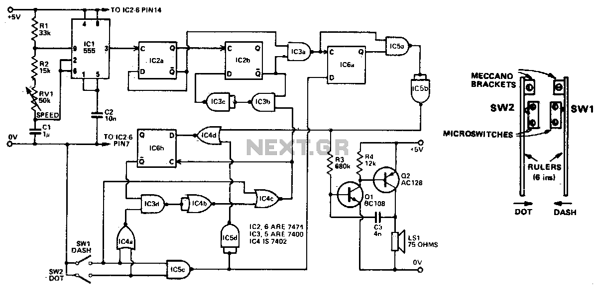
Automatically generated dits and dahs are produced over a speed range of 11 to 39 wpm. The upper limit can be raised by decreasing R2. SW1 and SW2 can be a "homebrew" paddle operated key. The described circuit is designed...
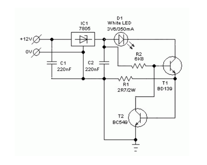
A simple and safe white LED driver circuit has been designed for use in 12V automobiles, allowing for the efficient operation of standard high-efficiency white LED modules powered by automotive battery systems. The circuit utilizes a fixed voltage regulator...
The NE555 timer circuit functions as a vibration generator. The input pin 3 produces pulse frequencies ranging from 5 to 20 Hz. The circuit includes a fan that operates within a bamboo enclosure. The barrel section is designed to...

The circuit for a car wiper speed controller allows for adjustable wiper speed, ranging from one to ten cycles per second. This feature enables flexibility in operation and contributes to energy efficiency. The car wiper speed controller circuit typically employs...
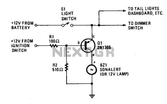
The circuit provides a visible or audible warning when the headlights are on. It utilizes a 2N1305 transistor as a switch to activate either a Sonalert tone generator or a small 12-V lamp. The operating current for the transistor...
Warning: include(partials/cookie-banner.php): Failed to open stream: Permission denied in /var/www/html/nextgr/view-circuit.php on line 713
Warning: include(): Failed opening 'partials/cookie-banner.php' for inclusion (include_path='.:/usr/share/php') in /var/www/html/nextgr/view-circuit.php on line 713