
Flyback Transformer circuit with 555

The circuit utilizes the 555 timer IC configured in astable mode, where the timing capacitor is charged through a 4.7kΩ trimmer resistor and discharged through a 2.2kΩ trimmer resistor, allowing for full adjustment of the duty cycle. The output square wave from the 555 timer drives a totem pole configuration consisting of a 2N3904 NPN transistor and a 2N3906 PNP transistor. This configuration provides rapid switching capabilities, ensuring that the gate of the IRF840 MOSFET is driven effectively, resulting in fast charging and discharging cycles. The IRF840 is selected for its high current handling capability and voltage rating, making it suitable for driving flyback transformers.
The flyback transformer is designed to operate efficiently at a resonant frequency of approximately 15kHz, with optimal performance occurring at around a 90% duty cycle. The circuit includes a snubber network composed of a 100Ω resistor rated at 5W to mitigate voltage spikes that may occur during operation. The inclusion of an LED serves as an indicator for operational status and safety. A dead man switch is recommended to ensure safety during operation.
The power supply requirements dictate a minimum output of 2-3A to achieve effective arc generation, with potential output voltages reaching up to 20,000kV. The circuit allows for flexibility in frequency adjustments through the use of a multiposition switch, enabling the selection of different capacitance values for C3, which can influence the operating frequency range. This adaptability makes the circuit suitable for various applications, including the driving of ignition coils and charging high-voltage capacitors.
Overall, this circuit design demonstrates a practical approach to utilizing flyback transformers for high-voltage applications, ensuring reliability and performance through careful component selection and configuration.The 555 is wired as an astable and the capacitor is charged only through the 4,7Kohm trimmer (notice the diode) and discharged only through the 2.2 Kohm trimmer, making the duty cycle full adjustable. The square wave is then feed in a totem pole made up of a 2N3904 and a 2N3906, which are cheap, and easy to find.
The totem pole ensures the gate being charged and discharged very fast (approx 50nS i think). The IRF840 is a cheap (i found it for 4euros) reliable and powerful power mosfet, it has current capability of 8 A continuous and 32A pulse, 800V drain source voltage, protecting internal zener diode. This is an efficient flyback driver for modern cylindrical rectified television flybacks. Many sites doesn't provide circuits driving these transformers, they simply say that they are bad. I don't agree. In fact I built this circuit. I spent a lot of time for finding resonant frequency (around 15Khz) and duty cycle. These transformers best work at around 90% duty cycle. You may notice corona breakdown at terminals and pfffff sound (as well as the ozone smell) when adjusting the off time trimmer to near 500-300 ohms. Of course it will work for other tipes of flyback as frequency and duty cycle have a large range. The 100 ohm snubber must me a 5W resistor, or it will burn at long operations The led is only for safety purposes Use a dead man switch (pushbutton) for safety The power supply must supply at least 2-3 A if you want decent arcs (20000 KV) Frequency range can be increased using multiposition switch for other values of C3 capacitor ,for example 2 nF for 80KHz-200000KHz, but didn't found flybacks with so high resonant frequencies, in addition with higher values of c3 , eg 200nF, 2uF the frequency will drop making possible the use of ignition coils, and rectified power transformers @50Hz to charge high voltage electrolitic caps at 300-400V).
Unfortunately my ignition coil died because insulation breakdown (too long drawn arcs). There is a snubbing network to ensure that voltage spikes are kept low (unless the insulation of the transformer start to leak) protecting both transistors and 555 IC. 100 ohm is a compromise between decay time and voltage spike. I was able to power a small (20cm) Spark Gap tesla coil Using these dc rectified flybacks to charge primary tank capacitor.
🔗 External reference
Related Circuits
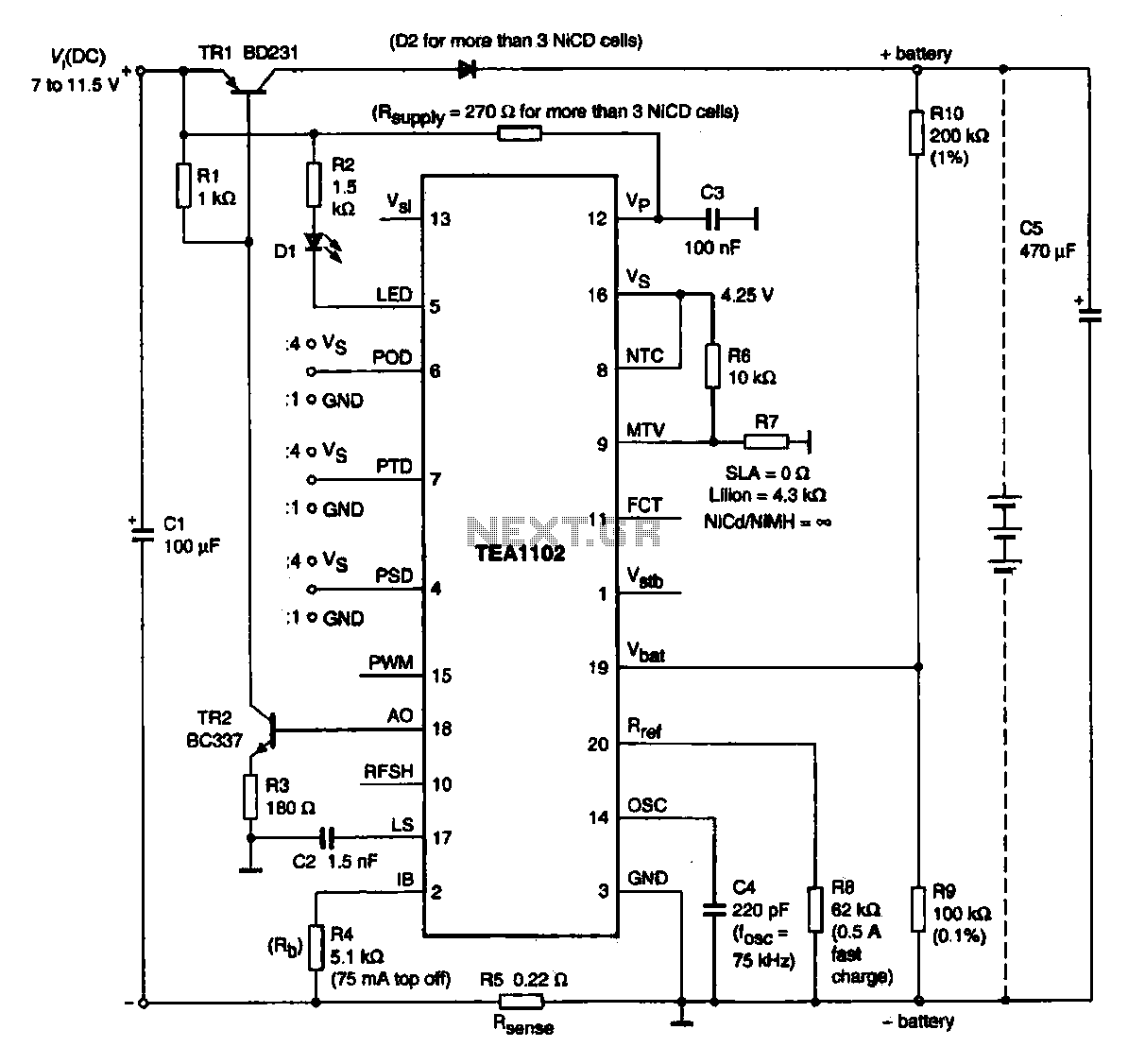
A fast charging circuit utilizing the TEA1102 controller is designed for various battery types. This circuit operates with a DC power supply voltage ranging from 7 V to 11.5 V and is compatible with nickel-cadmium, nickel-hydrogen, and lithium-ion batteries. The...
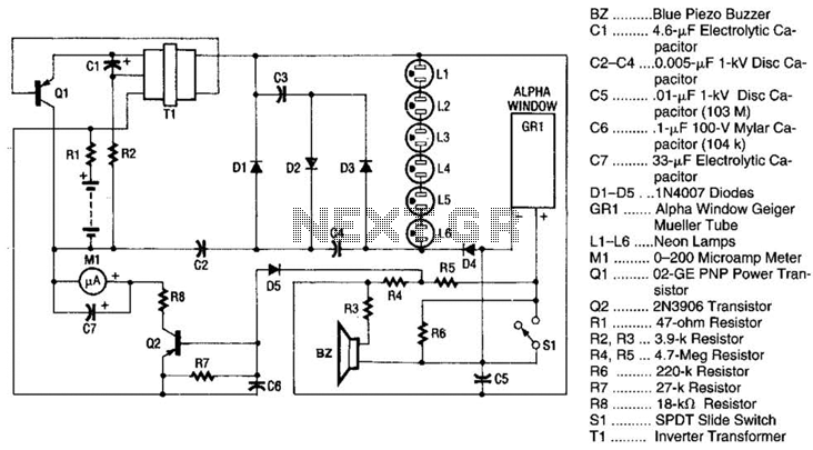
Q1 is a PNP power transistor used in conjunction with a ferrite transformer to form a blocking-type oscillator. This oscillator operates at a fixed frequency, with feedback for sustaining oscillations provided by capacitor C1. Due to the turns ratio...
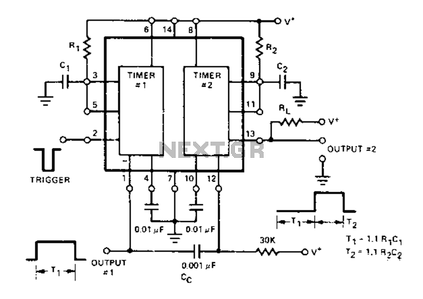
The Dual Timer Exar XR-2556 features a timing mechanism that can be triggered through capacitive coupling on a secondary timing pin. When a trigger input is engaged, the duration T1 can be set to 1.1R1C1, resulting in an increased...
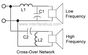
An audio crossover network is utilized within a speaker to separate or filter audio signals of varying frequencies to different speakers inside a speaker cabinet designed for those frequencies. This specific crossover network employs two passive components for each...
The receiver, as depicted in the figure, assists patients in avoiding missed audio signals during the daytime. The receiver operates independently, and the lighting will automatically turn off. At night, the lighting signal receiver activates simultaneously with the patient's...
Creating circuit boards can be a challenging task. It requires designing a schematic, testing it on a breadboard, laying out the board, and finally printing and etching the board. Fortunately, Fritzing offers a solution. Fritzing is a free, open-source...