
It used to delay the monostable multivibrator circuit diagram of a continuous sequence
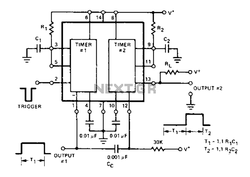
The Exar XR-2556 is a versatile dual timer IC designed for precise timing applications. It operates with a supply voltage of 4.5V to 16V, making it suitable for a variety of electronic circuits. The timing intervals are determined by external resistor-capacitor (RC) networks connected to each timer channel. The output of the first timer (Output 1) can be programmed to remain high for a duration T1, which is calculated using the formula T1 = 1.1 * R1 * C1, where R1 is the resistance in ohms and C1 is the capacitance in farads.
Upon triggering the first timer, the output will initially increase, providing a high signal for the duration specified by T1. Following this, the output will decrease, transitioning to a low state, which is controlled by the second timer (Output 2). This second timer can be triggered through a capacitive coupling mechanism, allowing for flexible timing applications. The duration T2 for the second timer is similarly defined by the equation T2 = 1.1 * R2 * C2.
Pin 13 of the XR-2556 plays a crucial role in extending the timing capabilities of the device, effectively allowing for the creation of monostable multivibrator functions. This feature is particularly useful in applications requiring precise timing control, such as pulse generation, delay circuits, or signal conditioning. The maximum output current is limited to 200mA, ensuring that the device can drive moderate loads without risk of damage.
Overall, the Exar XR-2556 dual timer is an effective solution for implementing timing functions in electronic circuits, providing designers with the flexibility to create complex timing sequences and control logic in a compact and efficient manner.Dual Timer Exar XR-2556 for the first time after the timing of the output can be triggered by capacitive coupling second timing pin. When the trigger input is used, in order to be able to equal the duration T1 1.1R1C1, output 1 will be increased, then decreased by CC-shot timer 2. Pin 13 is then also increased its duration T2 equal 1.1R2C2, its function and delay monostable multivibrator function is the same.
Supply voltage 4.5-16V. R can keep the timing of the supply voltage output below 200mA.
Related Circuits
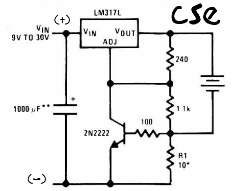
This is a straightforward charger designed for 9V to 30V batteries, primarily operated by the IC LM317L and a 2N222 transistor. It utilizes direct input DC voltage, and a recommended capacitor of 1000µF is included for filtering the output...
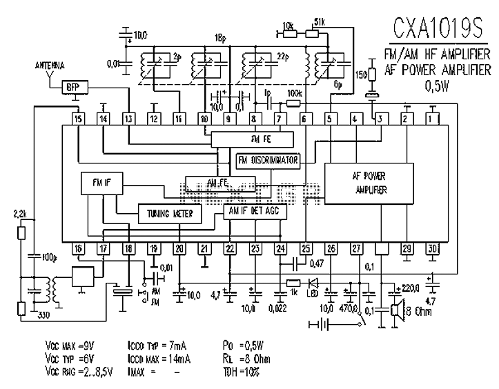
CXA1019 is a high-performance, high-sensitivity FM/AM radio special manifold developed by Sony, Japan. The CXA1019 features high integration, which includes an FM/AM tuner circuit, a mixer circuit, a mute circuit, an amplifier circuit (power output of 0.5 to 1W),...
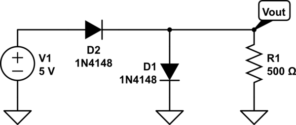
The two diodes will fail. It is advisable to include series resistors for them. If the simulation is successful, the current through the diodes will be excessive. Both diodes do not necessarily need to fail; one may become a...
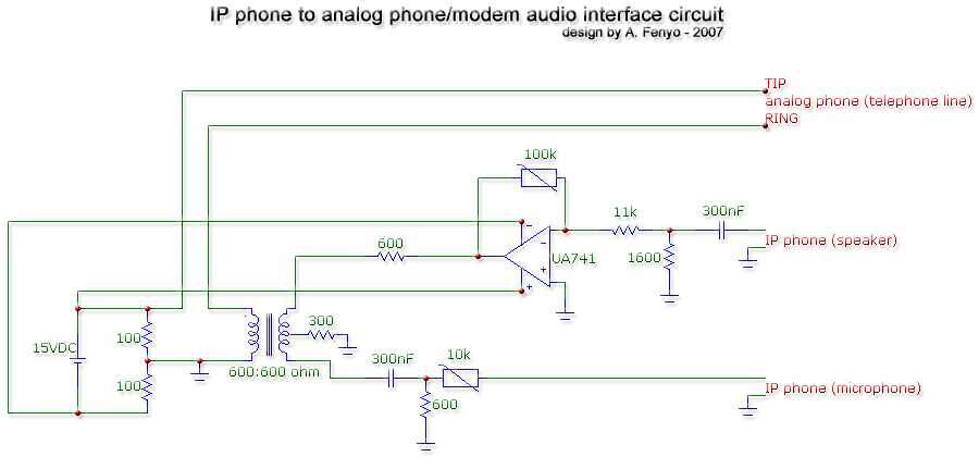
The transformer is a 600:600 ohm transformer, also referred to as a 1:1 ratio 600 ohm transformer. It has approximately the same number of turns on both the primary and secondary coils and is optimized for operation at a...
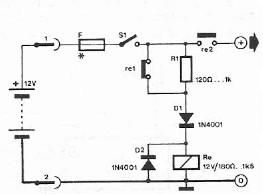
Safety polarity connection circuit design using common electronic components The safety polarity connection circuit is designed to ensure that electronic devices are connected with the correct polarity, preventing damage from reversed connections. This circuit typically employs common electronic components such...
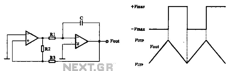
This circuit utilizes two operational amplifiers configured as triangular wave oscillators. It demonstrates a practical application of a relaxation oscillator that employs a voltage comparator to execute the switching function. The schematic in FIG. 2 illustrates the composition of...