
Medical call with lighting signal receiver circuit diagram
The described circuit serves as a dual-function receiver for auditory and visual signaling, particularly beneficial for patients who may struggle to hear alerts during the day. The integration of a photosensitive resistor (LDR1) allows the circuit to automatically adjust its operation based on ambient light conditions. During daylight, the LDR1 maintains a low resistance, ensuring that the thyristor remains inactive and that only auditory alerts are provided. This design minimizes unnecessary distractions from visual signals when they are least needed.
In contrast, the circuit transitions to a more alerting mode at night. As darkness falls, LDR1's resistance increases, disrupting the conduction of VT1. This change allows for the charging of the capacitor through resistors R1 and R3, which sustains the circuit's operation until dawn. The diode VD3 plays a critical role in ensuring that the thyristor BT136 remains triggered, thus illuminating the incandescent lamp L1. This feature is particularly advantageous for patients who may require both auditory and visual cues during nighttime, ensuring they are not overlooked.
The inclusion of ZD1 as a voltage regulator ensures that fluctuations in voltage do not affect the performance of the circuit, maintaining a stable operation. Furthermore, the option to replace the thyristor-based control with a relay system provides flexibility in design, allowing for alternative implementations based on specific requirements or component availability.
Overall, this circuit effectively combines light sensing, signal processing, and alerting mechanisms to create a reliable system for patient assistance, enhancing their ability to respond to calls for help both during the day and at night. As shown in FIG receiver may help patients avoid missing voice in the daytime, only the receiver itself is working, lights will automatically cut off part. At night the lightin g signal receiver and simultaneously sent with the patients request. Call switch is pressed, and also the primary transformer X1 AC power is turned on, the secondary voltage is rectified, filtered, the output DC voltage by R1 to the VT1 collector. If during the day, due to exposure to light, the photosensitive resistor LDR1 low resistance state, VT1 conduction, its collector is pulled to ground potential, the thyristor BT136 does not work, then only call ringtone can be heard, the lighting signal is inactive.
At night, LDR1 due to darkness and high-impedance state, so after pressing S1, VT1 off, the positive DC voltage filtered R1 and R3 may be charged to dawn. VD3 effect allows a constant positive DC bias trigger BT136, so that the incandescent lamp L1 light, so ask at night can hear the bell, but also to see the lighting signal for help.
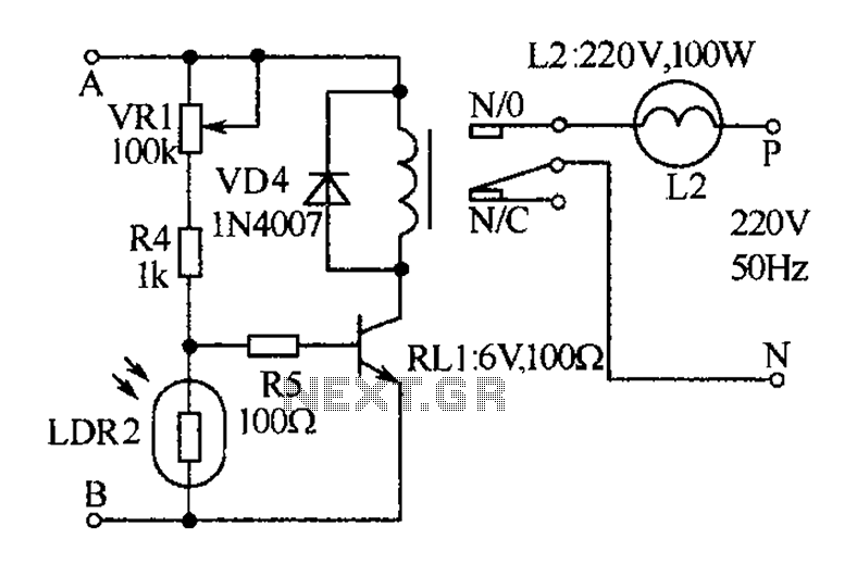
Zener diode ZD1 is used to limit the voltage across C2 is maintained at a stable value set. A, point B on the right side of the circuit section can be replaced at the circuit of Figure, but with the relay to control lighting without thyristors. During the day, due to the low resistance LDR2 bypass the base current to VT2 VT2 end, the relay RL1 is not working.
In the evening, LDR2 was almost an open state, the base current through VR1, R4 and R5 flows into the base so that VT1 conduction, RL1 pull bulb L2 light.
Related Circuits

A 555 timer (IC1) generates a 120-Hz signal that is fed to a CD4013BE flip-flop (IC1-a), which divides the input frequency by two to generate a 60-Hz clocking frequency for the FET array (Q1 through Q6). Transformer T1 is...
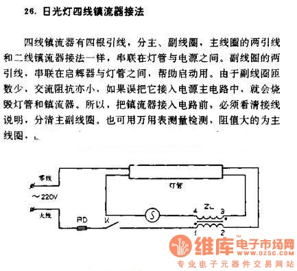
The four-wire ballast connection of a fluorescent lamp consists of four lead wires, which include main and auxiliary coils. The connection of the two lead wires in the main coil is similar to that of a second-line ballast; both...

The RF amplifier Q3 connects to diodes D1 to D4 within the mixer. Transistors Q1 and Q2, through transformers T1 and T2, facilitate the injection of liquid oxygen at 10 MHz for diodes D1, operational amplifier U1A, and U1B....

This document provides information regarding the wiring of the Toyota Tercel 1996. Component: intake air temperature sensor. The intake air temperature (IAT) sensor in the 1996 Toyota Tercel plays a crucial role in the vehicle's engine management system. It is...

This keyer utilizes skin conductivity to emulate the traditional mechanical CW bug keyer. When the dit paddle is activated, the bias on the inverter, IC1-a, is routed to ground, resulting in a logic high output. This triggers oscillator sections...
This schematic illustrates a high-quality AM radio receiver circuit centered around the MK484 AM radio integrated circuit (IC). The MK484 is known for its high sensitivity and superior performance, featuring only three leads and housed in a TO-92 package....