
AC contactor DC transformer circuit a run

AC contactors are electromechanical devices used to control the flow of electrical power in AC circuits. They function by opening and closing contacts to manage the power supply to various loads. The integration of a DC transformer in this circuit allows for the conversion of AC voltage to a regulated DC output, which can be utilized for powering DC loads or for further processing.
In this configuration, the AC voltage regulator circuit ensures that the output voltage remains stable despite fluctuations in the input voltage. This is particularly important in applications where sensitive electronic components are involved, as they require a consistent voltage level for optimal performance. The AC contactor is typically activated by a control circuit, which may include relays or microcontrollers that provide the necessary signals for operation.
DC contactors, which are used to control DC loads, are available in different types based on their operational characteristics, such as normally open (NO) or normally closed (NC) configurations. The choice of contactor type depends on the specific application requirements, including the load characteristics and the desired control logic.
Overall, the combination of an AC contactor with a DC transformer and a voltage regulator circuit provides a robust solution for managing electrical power in various applications, enhancing reliability and efficiency in electrical systems.AC contactor DC transformer circuit a run AC voltage regulator circuit operation DC contactors have a variety of types,
Related Circuits
This is an inexpensive DC voltage doubler circuit diagram that requires a minimal number of components and is capable of delivering 10V from a 5V power supply. If the oscillator needs to be... The circuit operates on the principle of...
This is a useful instrument for workshops. The standard of the produced frequencies is 10 to 1. The basic frequency is produced by a crystal with high accuracy. The circuit consists of the oscillator, around the crystal and the...
The circuit operates on the principle of detecting smoke produced during a fire. Smoke reduces the amount of light reaching a Light Dependent Resistor (LDR) placed between a light bulb and the LDR. This configuration is known as an...
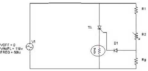
Simple resistor and diode combinations are used to trigger and control silicon-controlled rectifiers (SCRs) across the full 180-degree electrical range, exhibiting reliable performance at commercial temperatures. These circuits function optimally when SCRs possess relatively high gate sensitivities. In this...
In the previous post, the primary principles of the switching power supply were discussed. Essentially, an oscillator drives a transformer with a ferrite core at a relatively high frequency, thereby minimizing the size, weight, and cost of power supplies....

If the input is coming from a function generator's typical output clip leads, then the "black" lead or "-" or "ground" is connected to the circuit's ground. The ground of Pin 3 of a 555 timer must also be...