
FM Converters
The described FM converter circuit is a straightforward yet effective solution for adapting older FM radios to receive the new frequency band introduced post-World War II. The core of the design utilizes a single 6J5 tube and a 1N34 diode, allowing for the conversion of signals from the 88-108 MHz range down to a more manageable frequency that older receivers can process. The local oscillator's adjustment is crucial, as it enables the second harmonic to be utilized for mixing, a technique that is both efficient and effective in this context.
In terms of assembly, the circuit is mounted onto a U-shaped aluminum chassis, which provides a sturdy and lightweight structure for the components. This design choice not only facilitates easy integration within existing radio consoles but also aids in heat dissipation, which is essential for maintaining the reliability of the tube during operation.
The RF leakage from the local oscillator is a critical feature, as it allows the crystal diode mixer to function without the need for additional amplification stages, simplifying the overall design. The output at the 4.3 MHz IF frequency is compatible with many older FM receivers, ensuring that users can enjoy a wider range of broadcasts without the need for extensive modifications to their existing equipment.
The historical context provided by the references to Radio News and Radio Age adds depth to the understanding of this circuit's significance in the evolution of FM broadcasting. The mention of additional resources, such as typewritten notes from WMOT, offers practical insights into the construction and installation processes, which can serve as valuable guidance for modern enthusiasts looking to replicate this vintage technology.
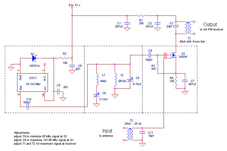
Overall, this one-tube FM converter exemplifies ingenuity in electronics design, demonstrating how simple circuits can effectively bridge the gap between old and new technologies in radio broadcasting.The FM broadcast band was moved immediately after World War II from its original spot just below 50 Mc to the present 88-108 Mc band. Hallicrafters was one company to offer receiving converters for those who had the old FM radio sets. The offerings included a one-tube converter that fits inside a console and draws power from the audio output tube
socket (using an adapter). This small converter is discussed in the June 1945 issue of Radio News. The article includes a schematic of the converter. However, at least one author suggests that this radio was never manufactured (Radio Age - January 2004). This is the simplest possible design. The local oscillator of the receiver is adjusted slightly so that its second harmonic can be used for mixing.
RF leakage from the local oscillator is sufficient to drive this crystal diode mixer, which has an output at the 4. 3 Mc IF frequency of the receiver. It is remarkably simple and apparently worked well for strong stations. See the review article: "Simple FM Converter Will Make You Money" Radio Maintenance, January, 1948. [View this one-page article (592Kb)] I have additional typewritten notes from WMOT in Pittsbourgh, PA on building and installing this type of converter.
(Thanks goes to Charles Harper for the written information and Darryl Hock for the photographs). This is a one tube (6J5) plus diode (1N34) circuit that converts any 8 Mc of the new FM band to the old FM band. It is assembled on a U-shaped piece of aluminum and mounted inside the radio set. I built one using old parts and carefully followed the article. It works! 🔗 External reference
Related Circuits
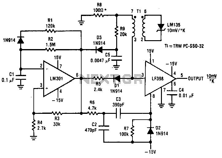
Both converters utilize CMOS inverters. Figure 105-1A illustrates a free-running circuit where both pulse duration and pulse pause are influenced by the temperature of diode D8. This configuration is suitable for applications where synchronization between the converter and other...
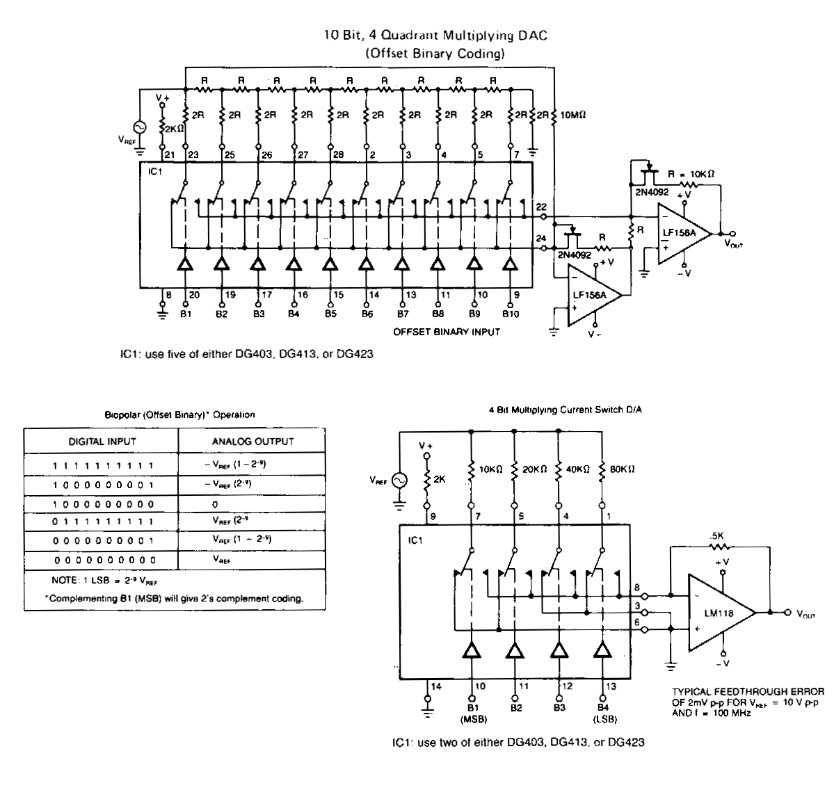
The following application circuits are designed to demonstrate several key concepts: A 2 kΩ resistor should be placed in series with the voltage source to limit supply current and mitigate negative ringing on the bit inputs. Temperature compensation for...
This circuit is designed to produce square waves by converting a sine wave obtained from an existing generator. A key feature is that it requires no external power source, allowing for simple connection between a sine wave generator and...
This type of converter is used to convert analog voltage to its corresponding digital output. The function of the analog-to-digital converter is exactly opposite to that of a digital-to-analog converter. Like a digital-to-analog converter, an analog-to-digital converter is also...
Analog-to-digital converters (ADCs), printed-circuit board (PCB), microcontroller or digital signal processor (DSP), total-harmonic-distortion (THD), signal-to-noise ratio (SNR). Analog-to-digital converters (ADCs) are essential components in modern electronic systems, enabling the conversion of analog signals into digital form for processing by microcontrollers...
Optimize the layout of the MAX16974/MAX16975/MAX16976 high-performance DC-DC converters, which are standard buck controllers designed for automotive applications. The MAX16974, MAX16975, and MAX16976 are advanced DC-DC buck converters specifically tailored for automotive environments. These devices are engineered to deliver high...