
Self-powered Sine to Square wave Converters
This circuit operates on the principle of signal conversion, leveraging a voltage doubler configuration to harness energy from the input sine wave. The capacitors C1 and C2, along with diodes D1 and D2, function as a rectifying and energy-storing mechanism, effectively doubling the voltage of the input signal. This increased voltage is crucial for powering the integrated circuit (IC) without the need for an external power supply, making the circuit highly efficient and portable.
The operational amplifier IC1A plays a vital role in amplifying the sine wave input, enhancing its amplitude to ensure that subsequent processing stages receive a robust signal. The inverters within the IC are configured to transform the amplified sine wave into a square wave. This transformation is characterized by maintaining a consistent mark/space ratio, which is essential for applications requiring precise timing and signal integrity.
The circuit is capable of operating effectively across a frequency range of 20Hz to 20kHz, making it suitable for various applications, including testing and signal generation in audio and communication systems. The design emphasizes fast rise and fall times, which are critical for minimizing distortion and ensuring the square wave output closely resembles an ideal square wave. This feature enhances the circuit's performance in real-world applications, where signal fidelity is paramount.
Overall, the described circuit represents a practical and efficient solution for converting sine waves to square waves, with applications spanning multiple fields in electronics and signal processing.This circuit is intended to provide good square waves converting a sine wave picked-up from an existing generator. Its major feature consists in the fact that no power-source is needed: thus it can be simply connected between a sine wave generator and the device under test.
The input sine wave feeds a voltage doubler formed by C1, C2, D1 & D2 that powers the IC. IC1A amplifies the input sine wave, other inverters included in IC1 squaring the signal and delivering an output square wave of equal mark/space ratio and good rise and fall times through the entire 20Hz-20KHz range. 🔗 External reference
Related Circuits
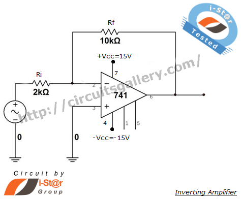
An inverting amplifier is one of the most widely used operational amplifier circuits. The output adjusts in a manner that counteracts changes caused by the input, thereby preventing saturation and ensuring stability. By connecting a resistor from the output...
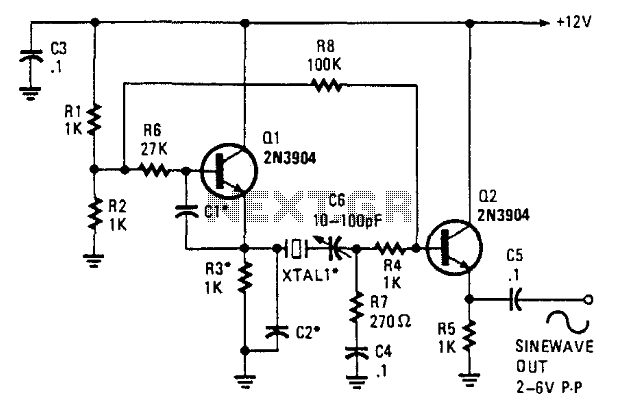
This oscillator employs two transistors and operates the crystal in its fundamental mode. Capacitors CT and C2 should be approximately 2,700 pF for 1 MHz, 680 pF for 5 MHz, and 330 pF for 10 MHz. A capacitance of...
This type of converter is used to convert analog voltage to its corresponding digital output. The function of the analog-to-digital converter is exactly opposite to that of a digital-to-analog converter. Like a digital-to-analog converter, an analog-to-digital converter is also...
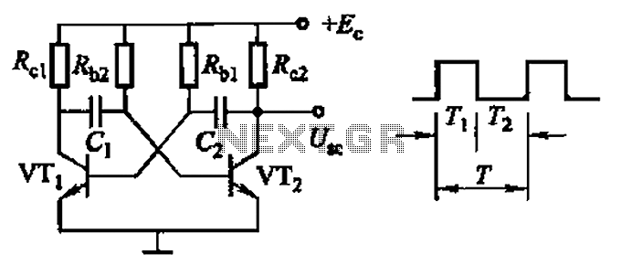
Common non-sinusoidal oscillator circuit, waveform and frequency formula - square wave oscillator - self-excited multivibrator The common non-sinusoidal oscillator circuit, specifically the square wave oscillator, is a fundamental electronic circuit utilized to generate square wave signals. It operates based on...
At VHF, both the 1/4-wavelength monopole and the 5/8-wavelength monopole antennas are widely used. The VHF 5/8-wavelength (144 MHz) vertical monopole has long held the reputation of providing about a 3-dB gain advantage over the 1/4-wavelength vertical monopole. The...
The closed-loop system consists of longitudinal and transverse components. The circuit operates as follows: a control circuit from the stepping motor CNC system issues a command, which the receiver detects. This signal is processed through a phase-sensitive rectifier to...
Warning: include(partials/cookie-banner.php): Failed to open stream: Permission denied in /var/www/html/nextgr/view-circuit.php on line 713
Warning: include(): Failed opening 'partials/cookie-banner.php' for inclusion (include_path='.:/usr/share/php') in /var/www/html/nextgr/view-circuit.php on line 713