
Layout Guidelines for the MAX16974/MAX16975/MAX16976 DC-DC Converters
The MAX16974, MAX16975, and MAX16976 are advanced DC-DC buck converters specifically tailored for automotive environments. These devices are engineered to deliver high efficiency and reliability, essential for automotive applications where power management is critical.
In optimizing the layout for these converters, several key considerations must be taken into account to ensure optimal performance. First, the placement of components should minimize the loop area of the high-frequency paths, which helps reduce electromagnetic interference (EMI) and improves overall efficiency. The input and output capacitors should be placed as close as possible to the converter's input and output pins, respectively, to minimize parasitic inductance and resistance.
Ground planes should be utilized effectively to provide a low-impedance return path for the current, which is crucial in high-frequency switching applications. Adequate thermal management must also be considered; the layout should allow for efficient heat dissipation to maintain the converters within their specified temperature range, thereby enhancing reliability and longevity.
Additionally, the use of vias should be minimized in high-current paths to reduce inductance and improve performance. The selection of trace widths according to current-carrying capacity is essential to prevent overheating and ensure safe operation.
By adhering to these layout optimization principles, the performance of the MAX16974, MAX16975, and MAX16976 converters can be maximized, thereby meeting the stringent requirements of automotive applications while ensuring robust and efficient power management.Optimize the layout of the MAX16974/MAX16975/MAX16976 high-performance DC-DC converters, standard buck controllers designed for automotive applications.. 🔗 External reference
Related Circuits
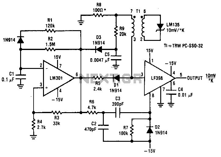
Both converters utilize CMOS inverters. Figure 105-1A illustrates a free-running circuit where both pulse duration and pulse pause are influenced by the temperature of diode D8. This configuration is suitable for applications where synchronization between the converter and other...
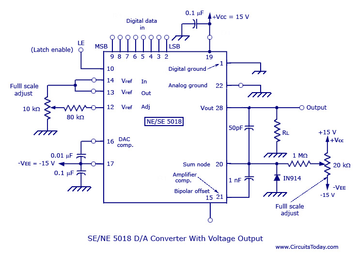
Monolithic and hybrid digital-to-analog converters utilizing MC 1408 IC and SE/NE 5018, including specifications and applications. Digital-to-analog converters (DACs) are integral components in various electronic systems, enabling the conversion of digital signals into corresponding analog voltages or currents. The MC...
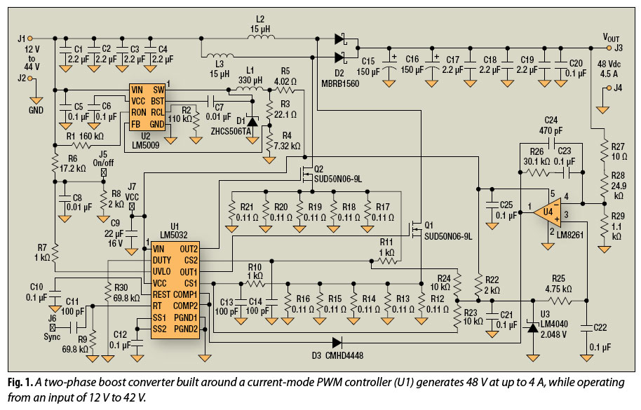
The multiphase approach has long been utilized to enhance efficiency, minimize ripple, and reduce the size of capacitors and inductors in buck converters. This method can also offer similar advantages for boost converters. The multiphase technique involves the use of...
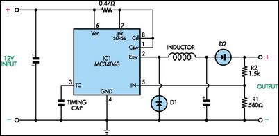
This circuit utilizes mobile phone chargers that incorporate the Motorola MC34063 switch-mode integrated circuit (IC). The output voltage can be adjusted across a broad spectrum by altering the values of the feedback resistors R1 and R2. The output voltage...
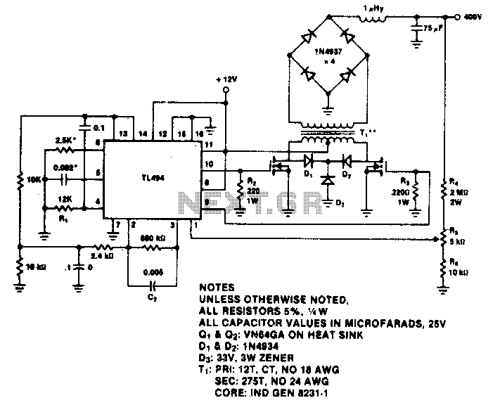
The TL494 switching regulator controls the operating frequency and regulates output voltage. The switching frequency is approximately 100 kHz for the specified values. Output regulation typically varies by 15% from no-load to full 60 W. The TL494 is a versatile...
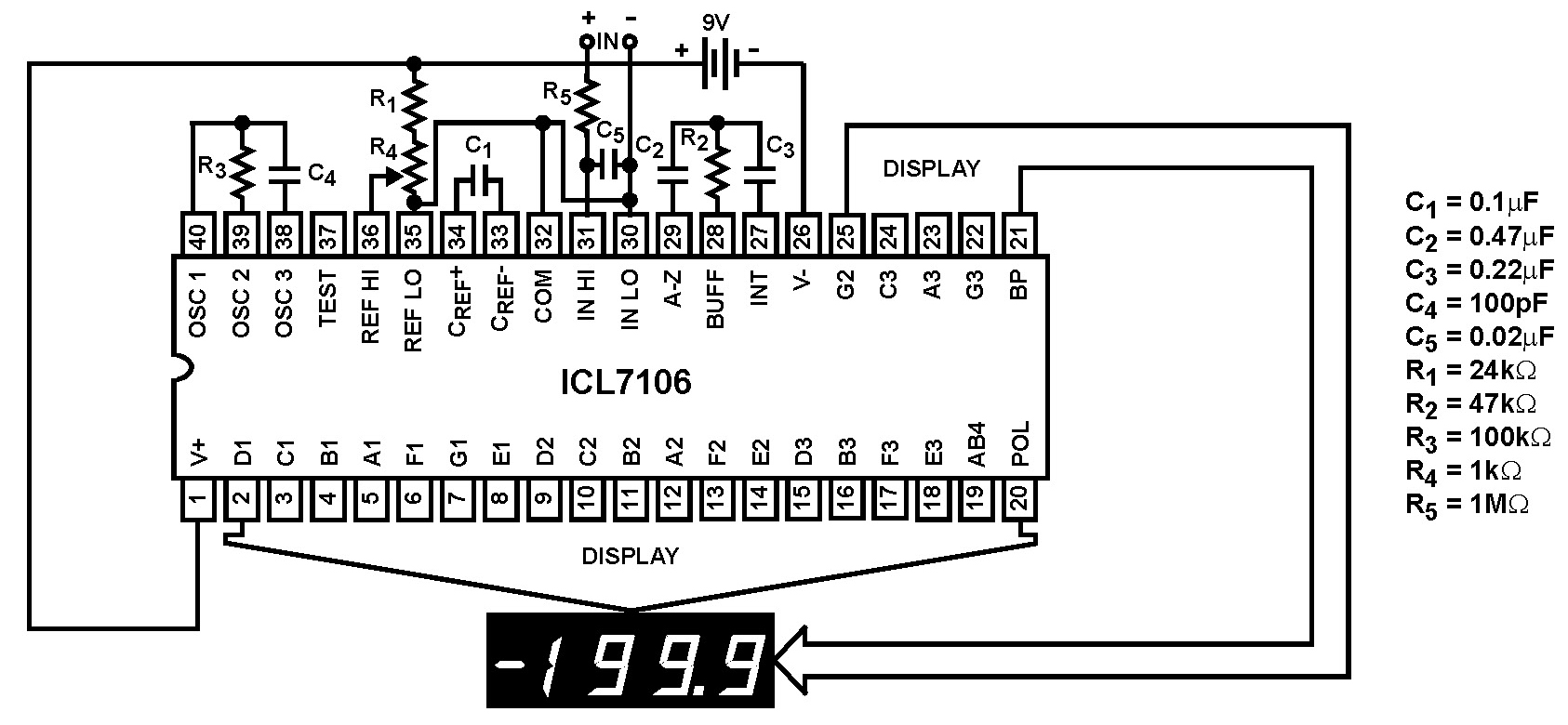
The Intersil ICL7106 and ICL7107 are high-performance, low-power, 3½ digit analog-to-digital (A/D) converters. They include seven-segment decoders, display drivers, a reference, and a clock. The ICL7106 is designed to interface with a liquid crystal display (LCD) and features a...