
FM radio antena amplifier
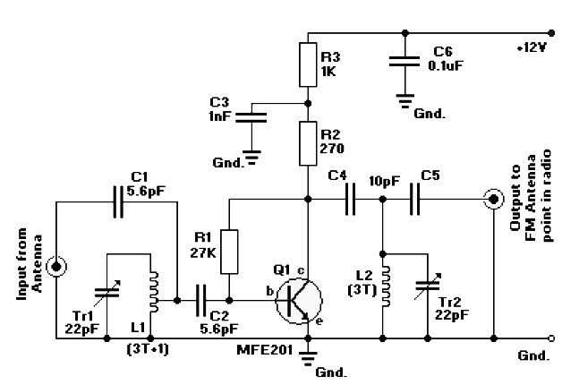
The FM radio antenna amplifier circuit is designed to enhance the reception of distant FM radio stations. Utilizing the MFE201 transistor, which operates in a common-emitter configuration, the circuit functions as a tuned RF pre-amplifier. This configuration allows for improved gain and selectivity, enabling the tuner to effectively distinguish between closely spaced frequencies, thereby enhancing the clarity of the received signals.
The circuit diagram includes essential components such as resistors, capacitors, and the MFE201 transistor, which work together to establish the necessary biasing and tuning conditions. The tuning is achieved through the careful selection of capacitive and inductive elements, which resonate at the desired FM frequencies. Proper grounding and shielding techniques should be implemented to minimize noise and interference from external sources.
In addition to the FM amplifier, the description also outlines a class B audio amplifier circuit capable of delivering 15 watts of output power. This circuit employs the LM833 dual op-amp configured to drive a pair of transistors, providing efficient amplification for audio signals. The class B configuration is beneficial for minimizing distortion, as it allows each transistor to conduct for half of the input signal cycle, thus improving overall fidelity.
The audio amplifier is designed to operate at a supply voltage of 14.4 volts, delivering a total output of 20 watts across two channels. Each channel is connected to a tweeter and a woofer, allowing for a full range of audio reproduction. The inclusion of an active crossover filter, with a crossover frequency set at 2 kHz, ensures that the appropriate frequency ranges are directed to the respective speakers, optimizing sound quality. The loudspeakers are specified to handle a power rating of 10 watts each and possess an impedance of 4 ohms, making them suitable for this application. The power supply can vary from 12 volts upwards, providing flexibility in system design.
In summary, this combined circuit design effectively enhances FM reception while delivering quality audio amplification, making it suitable for various audio applications. Proper attention to component selection and circuit layout will ensure optimal performance and reliability in the intended use cases.FM radio antena amplifier circuit diagram. This amplifier will pull in all distant FM stations clearly. Active FM amplifier circuit is configured as a common-emitter tuned RF pre-amplifier wired around the VHF / UHF transistor MFE201. Below is a circuit diagram of class B 15 Watts audio amplifier is designed using a dual op-amp and transistor.
The 15 W class B audio amplifier circuit shown here is a simple class B audio amplifier based onLM833 op. This is a20 watts audio amplifieris suppliedwith a voltage14. 4volts, givinga total power of20wattsinto twodifferent channels, each of whichis connectedto thetweeteranda woofer.
This amplifier isthereforeequipped with an active CROSSOVERfilterwithacrossoverfrequencyof 2KHz. Eachloudspeakermust supporta power of 10wattsandhaveanimpedanceof 4 ohms. The supply voltagecan bebetween12and up. 🔗 External reference
Related Circuits
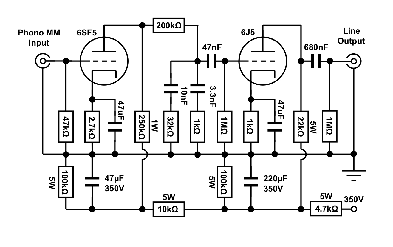
An octal preamplifier can be constructed as a standalone unit without the linestage component. However, this is not feasible due to its split RIAA configuration, which divides the RIAA equalization circuit into two sections: one following the first stage...
This simple audio power amplifier was originally designed for a circuit board workshop, conducted by the OSU IEEE Student Group. At the workshop, 20 participants each constructed this amplifier, by etching and drilling the single sided circuit board, soldering...
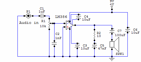
Here is a simple audio amplifier circuit that is easy to build and has few components. This circuit is built around the LM386 audio amplifier integrated circuit, useful when you need to power medium-sized speakers from a music player...
This is a very simple, low cost, Hi-Fi quality power amplifier. You can build it 5 ways, like its shown in the table (from 20 W to 80 W RMS). The first thing that you must do, is to...
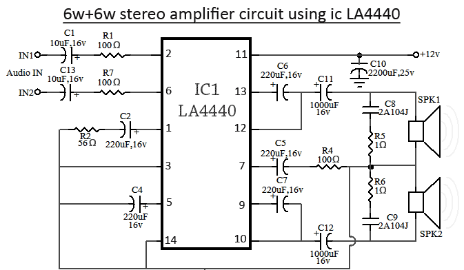
The LA4440 is a dual-channel audio amplifier integrated circuit (IC) that operates in two modes: stereo amplifier mode and bridge amplifier mode. This monolithic linear IC is produced by Sanyo. The circuit includes both amplifier modes utilizing the LA4440....
A radio camera on a model railway is designed to transmit continuously while the train is in motion and to continue transmitting for a few minutes after the train stops. If the train starts moving again after a relatively...