
5V Power Supply For On Train Radio Camera
The radio camera circuit for the model railway is designed to ensure reliable operation under varying conditions. The use of GoldCaps as a power source addresses the limitations posed by traditional battery technologies, providing a rapid charging solution and sustainable energy management. The circuit's architecture incorporates several key components that enhance performance and reliability.
The initial power input is buffered by capacitor C1, which serves to stabilize the voltage and mitigate any transient drops that may occur during operation. This feature is critical for maintaining consistent performance of the radio camera, especially during periods of high demand.
The series configuration of four GoldCaps is strategically chosen to achieve the required capacitance and voltage rating. Each GoldCap’s 22 F capacitance contributes to a total of 5.5 F, ensuring that the camera can operate for a few minutes even after the train has stopped. The voltage regulator (LT1086) is crucial for maintaining a safe charging voltage, preventing overcharging and potential damage to the GoldCaps. The design of the voltage regulator circuit, including the resistors R2 and R3, is essential for setting the output voltage accurately while accommodating the forward voltage drop of diode D5.
Diodes D2, D4, and D5 play a pivotal role in the power management strategy. D2 allows charging of the GoldCaps when DC voltage is present, while D4 ensures that the camera is powered directly from the track during operation, thus conserving energy stored in the GoldCaps. D5 provides additional protection by blocking any reverse current that could deplete the stored energy in the capacitors when the track voltage is absent.
The output stage, utilizing the 7805 voltage regulator, is designed to provide a stable 5 V output for the radio camera, which is critical for its operation. The inclusion of capacitors C9, C10, and C11 serves to filter and stabilize the output voltage, further enhancing the reliability of the camera's performance.
In summary, the circuit design effectively addresses the challenges of power management for a radio camera on a model railway, ensuring continuous operation during movement and immediate readiness after pauses. The integration of GoldCaps, voltage regulation, and protective diodes creates a robust system that meets the operational demands of the application.A radio camera on a model railway should transmit constantly while the train is moving and continue transmitting for a few minutes after the train stops. But if the train starts up again after a relatively long halt, imagery should be transmitted immediately.
Consequently, the power source for the camera cannot be rechargeable batteries (since the y take too long to charge), nor can it be primary batteries (for environmental reasons). Instead, GoldCaps provide a good alternative. They can be charged in no time flat, and they assure sufficient reserve power for operating the radio camera for a few minutes. Coming from the left in the schematic shown in Figure 1, the dc voltage arrives at the supply circuit and is buffered by capacitor C1, which bridges brief power interruptions.
The actual reserve power source consists of four GoldCaps connected in series, each rated at 22 F / 2. 3 V, which yields a net capacitance of 5. 5 F / 9. 2 V. The maximum charging voltage must never exceed 9. 2 V. This is ensured by a modern adjustable low-drop voltage regulator (LT1086), which is set to a nominal output voltage of 9.
57 V by resistors R2 and R3 (since there is an 0. 6-V voltage drop across D5). The LT1086 can handle a current of 1. 5 A (with current limiting), so even completely empty GoldCaps can be charged in a few seconds. Whenever the dc voltage is present, the GoldCaps are charged via D2. When the dc voltage is present, the camera is not powered from the Gold-Caps, but instead directly from the track via D4. Diode D5 prevents this voltage from reaching the bank of capacitors, and D4 prevents the GoldCaps from discharging via the track when no voltages present on it.
D4 and D5 thus form a sort of OR gate. The radio camera used by the author requires 5 V and draws a current of approximately 70 mA. This means the circuit must have an output stage consisting of a normal` 7805 fixed voltage regulator and the usual capacitors (C9 C10, C11). The two low-current LEDs respectively indicate whether voltage is present on the track and whether the storage capacitors are charged.
They can also be omitted. The 100-nF capacitors must be placed as close as possible to the voltage regulators. 🔗 External reference
Related Circuits
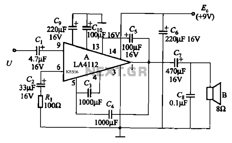
Audio power amplifier circuit utilizing the LA4112 integrated power amplifier along with additional components as shown in the figure. The audio power amplifier circuit based on the LA4112 integrated power amplifier is designed to deliver high-quality audio amplification for various...
This shows the overall circuit diagram of the power control unit. On the left, there is a main relay controlled by the key switch. The power control unit circuit diagram illustrates the fundamental components and their interconnections, providing a clear...
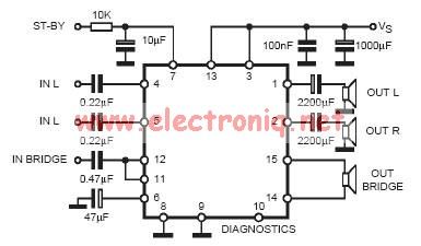
In practical applications, a series resistance must always be included. This component serves the dual purpose of limiting the current at pin 7 and smoothing the ON/OFF transitions during standby. In electronic circuits, particularly those involving integrated circuits (ICs) or...
This radio receiver can operate with any of the following transistors: ZN414, MK484, or TA7642. The radio receiver circuit is designed to utilize a variety of transistors, specifically the ZN414, MK484, and TA7642, which are commonly used in low-power AM...
This is a simple low supply rail detection circuit that is inexpensive and can be assembled in approximately 20 minutes. It operates with low power consumption, making it suitable for integration into battery-powered devices. The circuit utilizes three low-cost...
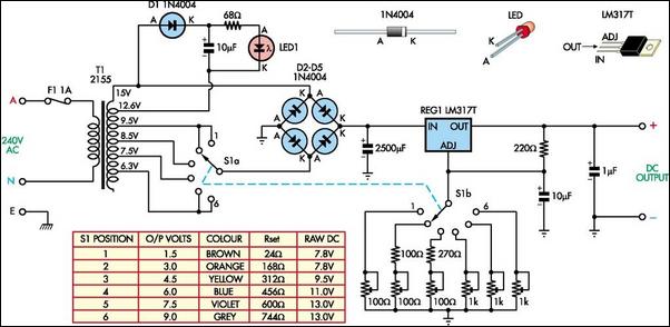
The battery-operated toy has malfunctioned, necessitating repair. Upon disassembly, the battery compartment may be disconnected from the circuitry, or the batteries might be depleted. A solution is to implement a switchable power supply designed to replace one to six...