
fm radio ic tda7000 schematic

The FM radio receiver circuit utilizing the TDA7000 IC is a compact and efficient design suitable for various applications, including personal audio systems and portable radio devices. The TDA7000 IC simplifies the overall circuit design by integrating multiple functions required for FM reception, including the RF amplifier, demodulator, and audio output stage.
The circuit's operational voltage range of 2 to 12 volts makes it versatile for battery-operated devices, ensuring long operational life due to its low current draw. The FLL technology employed in the TDA7000 enhances the receiver's ability to maintain stable tuning and minimize drift, which is crucial for clear audio reception, particularly in environments with multiple radio signals.
The inclusion of an RC circuit for selectivity adjustment allows users to fine-tune the reception quality, accommodating various broadcasting conditions. This feature is particularly advantageous in urban areas where signals may overlap.
To enhance the audio output, integrating a stereo demodulator circuit is recommended for applications requiring high-fidelity sound. This additional circuitry can process the mono output from the TDA7000 and convert it into a stereo signal, improving the listening experience.
Overall, the TDA7000-based FM radio receiver circuit is an effective solution for receiving FM signals, characterized by its low power consumption, ease of use, and adaptability for various audio applications.FM radio receiver circuit is an FM receiver made by IC TDA7000. The circuit uses IC TDA7000 FM receiver can be supplied with a DC voltage of 2 volts DC to 12 volts DC. FM radio receiver circuit includes a series of simple because it uses the TDA7000 IC. IC TDA7000 IC is designed specifically as an FM receiver. IC TDA7000 is an FM tuner that uses a system of FLL (Frequency-Locked-Loop) to the IF frequency of 70 KHz. Complete schematic FM radio receiver using the TDA7000 IC can be seen in the following figure. FM radio circuit use IC TDA7000 as shown above can receive a radio frequency emission from a radio transmitter with a frequency range from 70 MHz reception up to 120 MHz. FM radio receiver circuit use IC TDA7000 has a high selectivity for tuning the system using the TDA7000 IC technology FLL (Frequency-Locked-Loop) with a degree of selectivity is controlled by the RC circuit.
FM radio receiver circuit by IC TDA7000 has a current consumption is low enough so that the range of 8 mA can be operated with batteries for a long time. Audio output signal from the FM receiver circuit TDA7000 IC is still mono, to get stereo-quality audio signal to be added stereo demodulator circuit.
🔗 External reference
Related Circuits
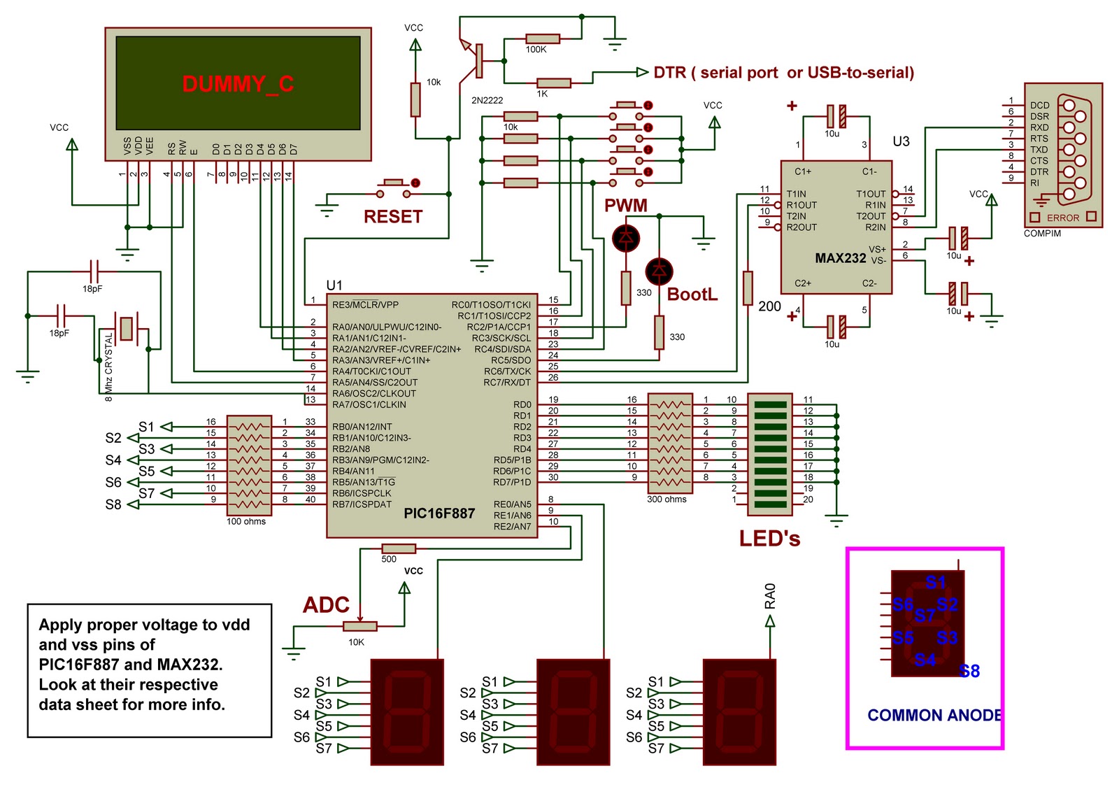
This is a demo board based on the PIC16F887 microcontroller. It serves as an excellent project for beginners working with PIC microcontrollers. The board includes a bootloader, eliminating the need for an external programmer. The circuit design is straightforward,...
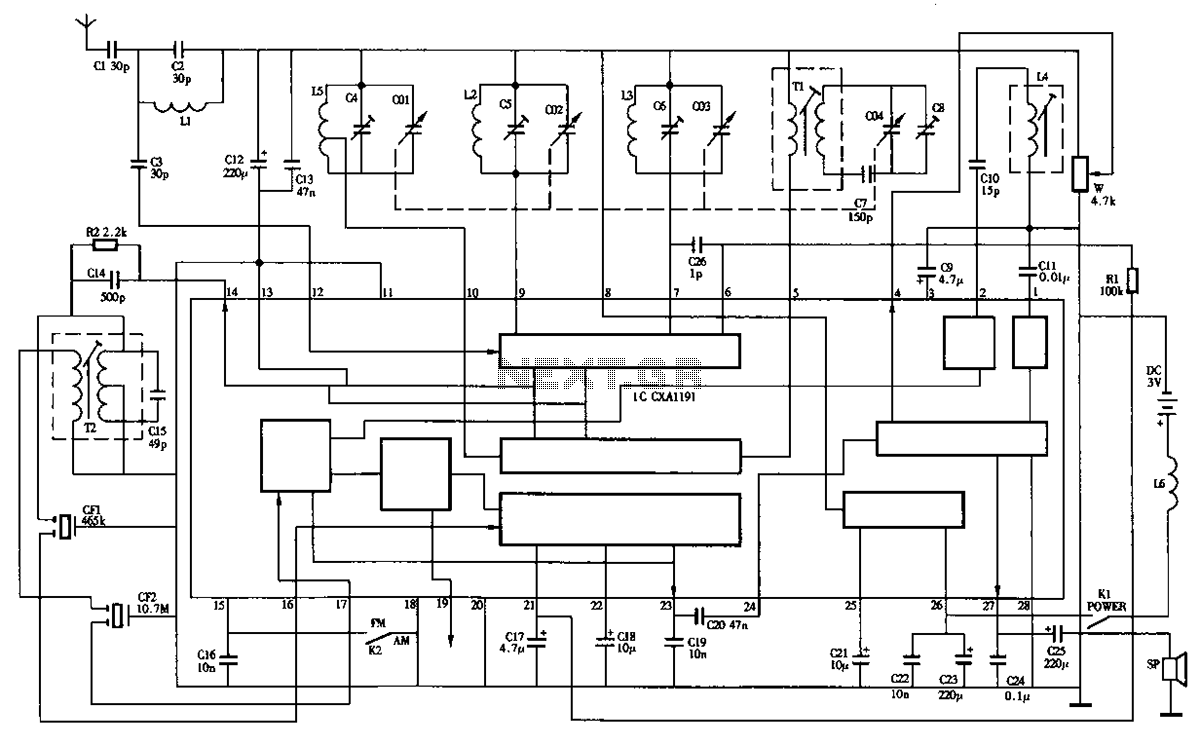
The circuit diagram of the Desheng R-202T type two-band radio is as follows. The Desheng R-202T is a two-band radio receiver designed to operate on both AM and FM frequencies. The circuit typically includes several key components that facilitate the...
This document provides information on the technical aspects of monitoring meteor counts through VHF radio receivers. It aims to address gaps in existing literature and offers alternative perspectives on observational techniques, supported by real data. While many online resources...
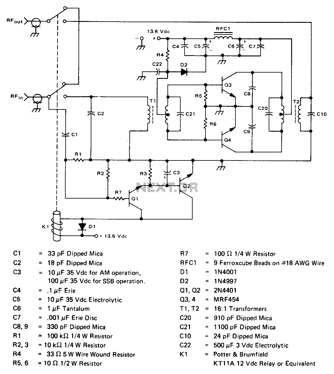
This inexpensive, easy-to-construct amplifier utilizes two MRF454 devices. It is specified for an 80 W power output with a 5 W input drive at a frequency of 30 MHz and operates on a 12 V DC supply. The amplifier circuit...
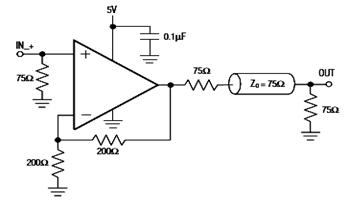
The diagram below illustrates a typical operating circuit for the video line driver using the IC4030/4031 schematic. It incorporates the MAX4030E/MAX4031E, which are unity-gain stable operational amplifiers that offer high-speed performance, rail-to-rail outputs, and 15kV ESD protection, as stated...
The MT-2 Metal Zone™ is one of the most popular guitar pedals, delivering intense distortion tones characterized by pronounced mids and lows, along with an ultra-saturated sound. It features a distinctive dual-gain circuitry that enables long sustain and emphasizes...
Warning: include(partials/cookie-banner.php): Failed to open stream: Permission denied in /var/www/html/nextgr/view-circuit.php on line 713
Warning: include(): Failed opening 'partials/cookie-banner.php' for inclusion (include_path='.:/usr/share/php') in /var/www/html/nextgr/view-circuit.php on line 713