
schematic diagram
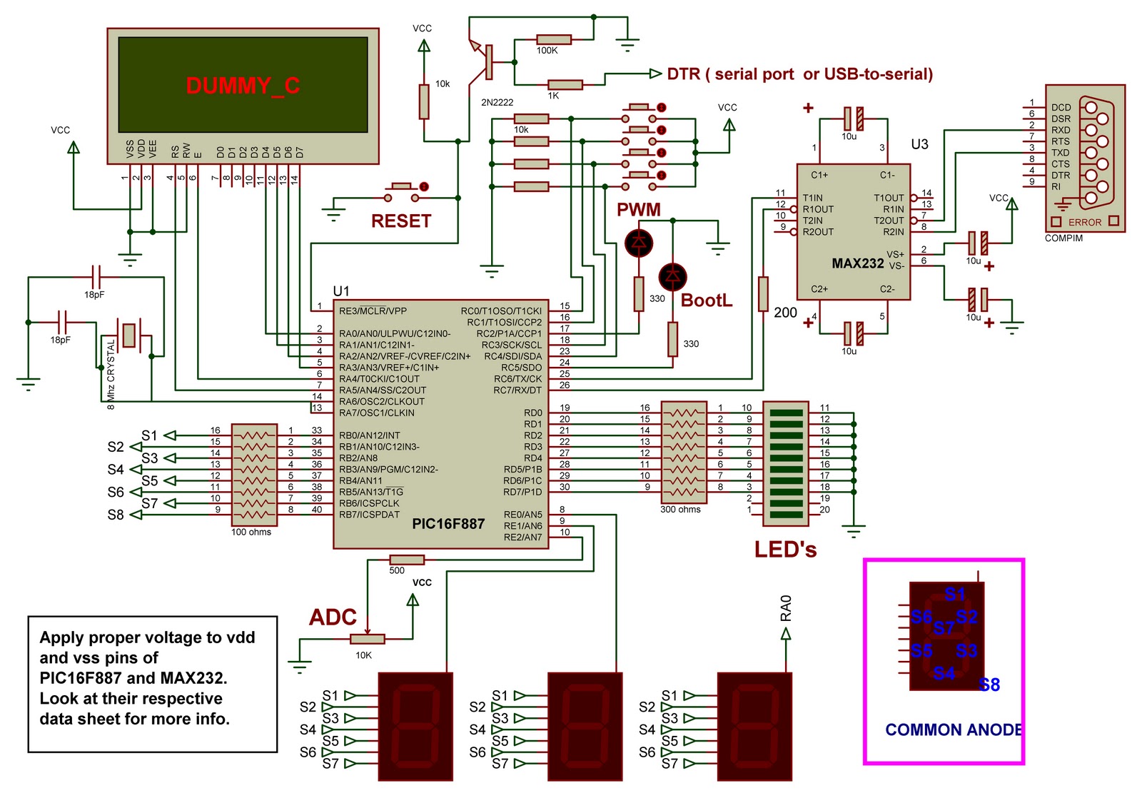
The PIC16F887 microcontroller is a versatile and powerful device within the Microchip PIC16 family, featuring a 14-bit instruction set architecture and a maximum clock speed of 20 MHz. It supports up to 368 bytes of RAM and 14-bit wide program memory, making it suitable for a variety of applications. The demo board provides an excellent platform for users to familiarize themselves with the microcontroller's capabilities, including its GPIO pins, timers, and serial communication interfaces (USART).
The inclusion of a MAX232 chip allows for reliable RS-232 communication, enabling the demo board to interface with PCs or other serial devices. The seven-segment displays provide a straightforward method for visual output, while the onboard LEDs can be utilized for status indication or simple signaling. The optional LCD header expands the board's usability, allowing for more complex user interfaces.
The design prioritizes ease of use and accessibility, making it ideal for educational settings. By providing a robust platform for experimentation, the demo board encourages hands-on learning and exploration of embedded systems. The modular nature of the design, with provisions for additional switches and headers, allows for future enhancements and adaptations, catering to a wide range of projects and learning objectives. Overall, this demo board serves as a valuable resource for anyone interested in delving into the world of microcontrollers and embedded systems.These is the demo board I made based on PIC16F887 microcontroller. It is a good project for starting with PIC uC`s. It has a bootloader so an external programmer is not needed. The circuit is simple but it will let you explore some of the major features that a PIC16 device has. I also used mikroC as the compiler since it is very easy to use. I wil l give a demo board like these to the school (to which is still under development) so it could be used to students who are willing to learn. I hope these will help you on your journey of learning PIC microcontrollers. I choose the PIC16F887 device because it is one of the latest PIC16 series from microchip. It is cheap, has a big memory, commonly available, etc. And most of all it is almost the same with and pin-compatible with PIC16F877A. In fact, you can find code examples intended for the PIC16F887 in mikroC help files. If you want to work with microcontrollers it is a great advantage if you own a development/demo board.
There will be no problem with the hardware setup. It eliminates the usual problems faced by PIC newbies: badly designed circuit, bread board loose connections as well as misconnections, problem with the programmer, etc. If you can`t afford to buy one, you can build one yourself. The major parts are the PIC16F887, MAX232, 7 segments and the LEDs. The LCD is optional but there is headers for it if needed. These board can cost more or less 15 USD. If anybody wants the PCB layout just comment. These board was designed to allow students, hobbyist and the like to start exploring the capabilities of the PIC microcontrollers by their own and with less difficulty.
These board can be used for many types of electronic projects, development and application prototyping. In addition, it can be used for demonstration, training, and education purposes. Here is a sample video of the other demo boards in action. The only difference with these boards with the others is the number of 7 segments used and it`s placement.
But basically they are the same. Every now and then I added some features on my demo boards. The last video was the latest which has an optional jumper switch to connect a button on the external interrupt pin(RB0). It also has a LED indicator the turns on when the board is connected to the mikro bootloader (PC side).
I plan to use more switches next time as well as use more female headers to have more auxiliary inputs/outputs. 🔗 External reference
Related Circuits
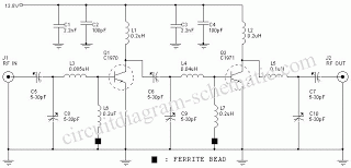
An FM amplifier is utilized to amplify signals from an exciter in broadcast radio stations. This RF FM amplifier employs solid-state materials with a minimum gain of 9 dB. The input requirement for the FM amplifier is between 5...
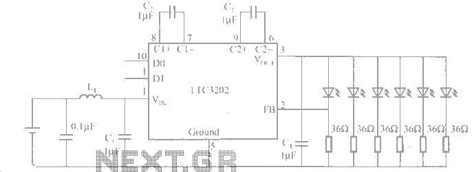
The LTC3202 is a device from Linear Technology that eliminates the need for a charge pump gated oscillator. It is designed as a charge pump for driving white LEDs powered by a lithium-ion battery. To address noise issues, the...
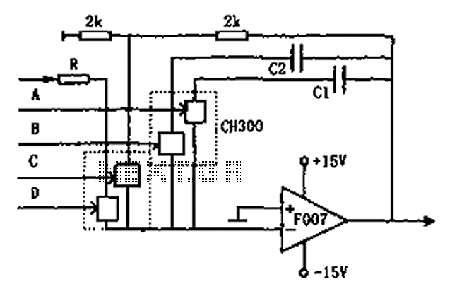
The circuit depicted in the figure is a controllable integrating circuit. It features a reset-to-zero function and allows for the adjustment of different integration time constants via a controllable integrator. The analog switch used is C. More specifically, it...
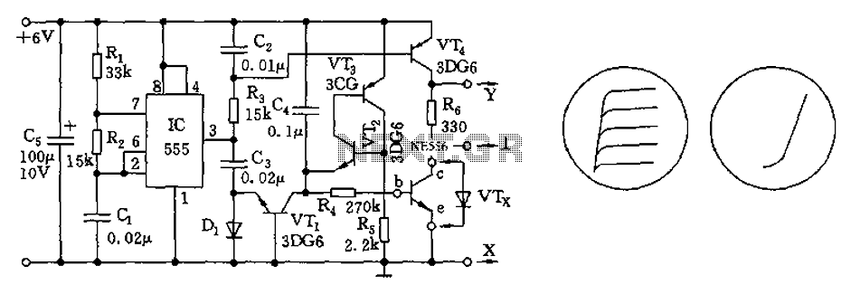
The transistor characteristic curve tracer circuit depicted in Figure 555 illustrates the characteristics of a transistor. It utilizes two voltages: a step wave applied to the base (b) to generate different base currents (Ib), and a sawtooth waveform at...
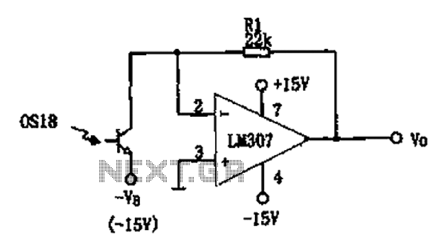
The circuit described is a photoelectric receiver amplifier designed to amplify the electrical signals generated by photodiodes or phototransistors in optoelectronic devices. When the intensity of incident light varies, the photosensitive device generates a corresponding voltage or current. The...
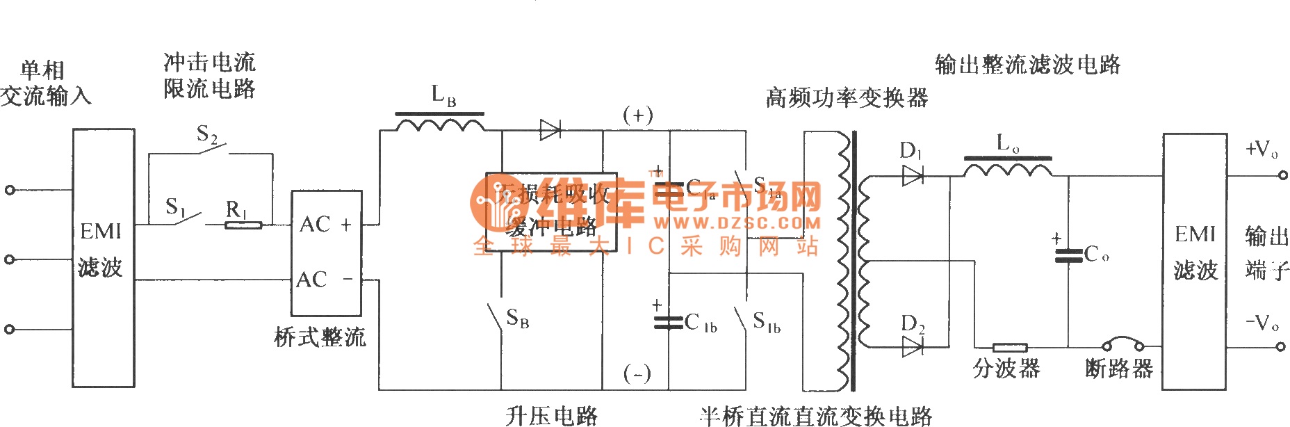
The figure illustrates a simplified schematic diagram of the main circuit DMA12. It primarily consists of the input circuit, an electromagnetic interference (EMI) filter circuit, an impulse current limit circuit, an input rectifier filter circuit, a boost/power factor correction...