
FM Radio Receiver Circuit
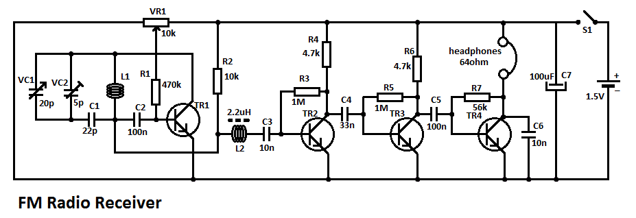
This circuit is designed to receive FM radio signals, utilizing a regenerative RF stage for signal amplification and selection. The regenerative stage, implemented with transistor TR1, enhances the sensitivity and selectivity of the receiver. The circuit operates by feeding a portion of the output signal back to the input, which increases the gain and enables the reception of weaker signals.
Following the RF stage, the audio signal is processed through a multi-stage audio amplifier. The configuration can be either a two-stage or three-stage amplifier, utilizing transistors TR2, TR3, and TR4. Each stage is responsible for further amplifying the audio signal derived from the RF stage, ensuring that the output is suitable for driving speakers or headphones.
The circuit may include passive components such as resistors and capacitors, which are essential for biasing the transistors, filtering, and coupling between stages. The design also typically incorporates an antenna input for capturing the FM signals and may feature a tuning mechanism to adjust the circuit for different frequencies.
Overall, this FM radio receiver circuit is a straightforward yet effective design for amateur radio enthusiasts and serves as an excellent educational project for understanding the principles of radio frequency and audio amplification.This simple fm radio receiver circuit consists of a regenerative rf stage, TR1, followed by a two of three-stage audio amplifier, TR2 to TR4. In some areas.. 🔗 External reference
Related Circuits
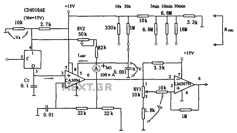
The long timer circuit utilizes an operational amplifier, specifically the CA3094, to control the discharge formula for extended timing. This is typically achieved by adjusting the variable resistor RV1, which alters the timing duration to meet specific requirements. The long...
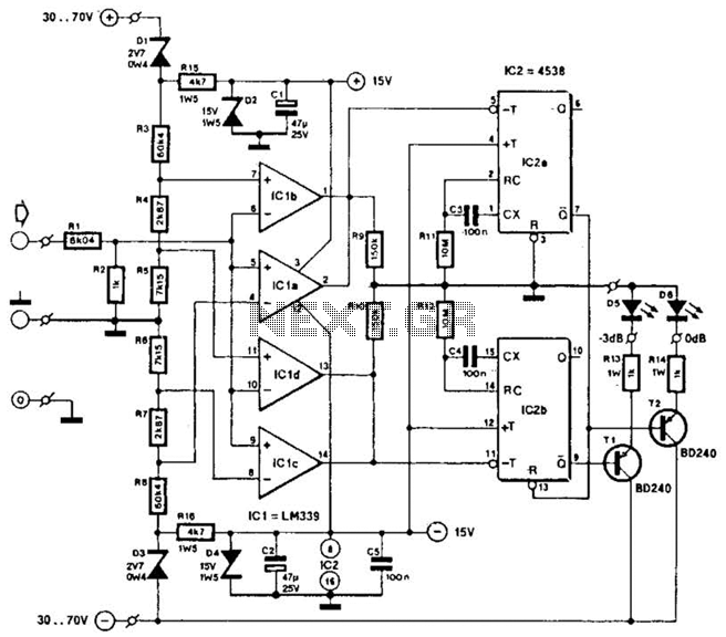
This circuit was utilized with an audio power amplifier to identify the point at which the output is -3 dB from maximum, indicated by LED D5, and at clipping, shown by LED D6. The indicator can be employed with...

The original scale on the voltmeter ranged from 0 to 30 volts. A new scale was created by removing the old scale from the meter and scanning it into a graphics editing software on a computer. The old numbers...
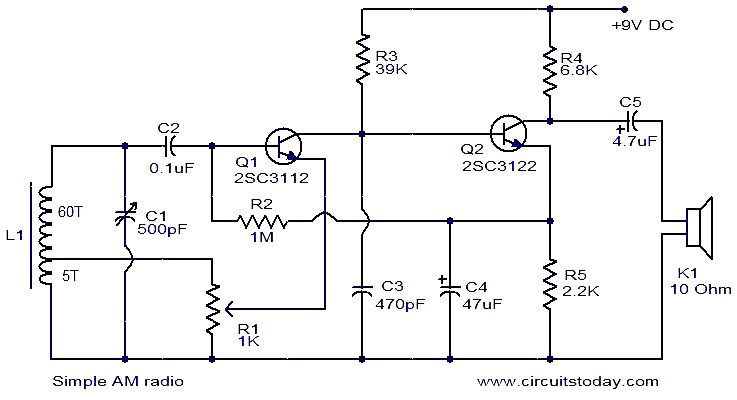
This is a straightforward AM radio circuit utilizing only two transistors. The coil L1 and variable capacitor C1 create the tank circuit. Transistor Q1 is responsible for demodulation, and the demodulated signal is accessible at the base of Q1....
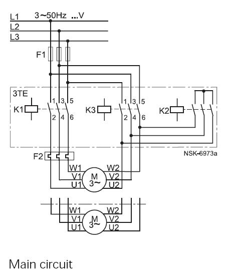
This method reduces starting current and starting torque. The device typically consists of three contactors, an overload relay, and a timer for setting the duration in the star position (starting position). The motor must be delta connected during normal...
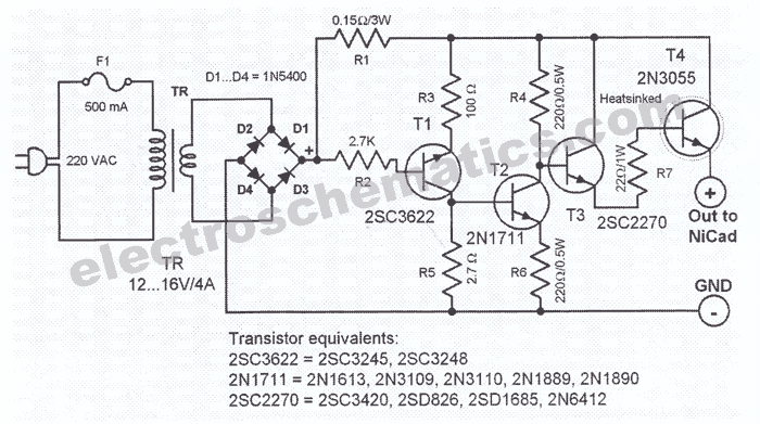
This NiCd battery charger circuit schematic can charge 6 volts as well as 12 volts NiCad batteries. It uses a transformer that can deliver 4 to 5 A current. The NiCd battery charger circuit is designed to accommodate both 6V...
Warning: include(partials/cookie-banner.php): Failed to open stream: Permission denied in /var/www/html/nextgr/view-circuit.php on line 713
Warning: include(): Failed opening 'partials/cookie-banner.php' for inclusion (include_path='.:/usr/share/php') in /var/www/html/nextgr/view-circuit.php on line 713