
NiCd Battery Charger Circuit
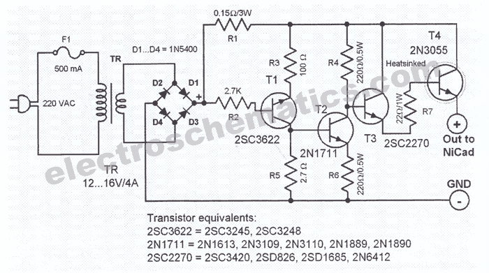
The NiCd battery charger circuit is designed to accommodate both 6V and 12V NiCad batteries, making it versatile for various applications. The core component of this circuit is a transformer, which is responsible for stepping down the AC voltage from the mains supply to a suitable level for charging the batteries. The transformer is rated to deliver a current in the range of 4 to 5 A, ensuring that it can efficiently supply the necessary power for charging.
The circuit typically includes a rectifier, which converts the AC output from the transformer into DC, suitable for charging the batteries. This is often achieved using a bridge rectifier configuration, which allows for full-wave rectification, improving the efficiency of the charging process. Following the rectification stage, a smoothing capacitor is used to filter out any ripple voltage, providing a stable DC output.
To prevent overcharging, the circuit may incorporate a charging control mechanism, such as a voltage regulator or a timer circuit. This ensures that the batteries are charged to their optimal voltage and prevents damage due to excessive charging. Additionally, the schematic may include protection diodes to prevent reverse current flow, which can occur when the batteries are disconnected from the charger.
The design should also consider thermal management, as charging can generate heat within the components. Adequate heat sinking for the rectifier and any voltage regulation components is essential to maintain performance and reliability.
Overall, this NiCd battery charger circuit schematic is a practical solution for charging both 6V and 12V NiCad batteries, with a focus on efficiency, safety, and reliability.This NiCd baterry charger circuit schematic can charge 6 volts as well as 12 volts NiCad batteries. It uses a transformer which can deliver 4 to 5 A curren.. 🔗 External reference
Related Circuits
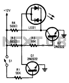
With switch SI open, base bias is supplied to transistor Q2 through a voltage divider formed by resistors R2 and R3, which activates the green element of the LED. This indicates that power is being supplied to the project....
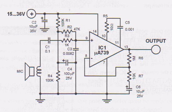
This circuit is a low voltage microphone preamplifier that operates with a 1.5V power supply. It features a reference with a 500 kHz unity-gain bandwidth, functioning as a preamplifier with a gain of 100. The output from this stage...
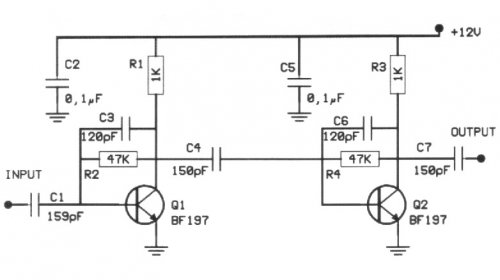
The following circuit illustrates a 20 dB VHF amplifier circuit diagram utilizing the BF197 transistor. Features include a simple circuit design. The 20 dB VHF amplifier circuit is designed to amplify very high frequency signals, making it suitable for applications...
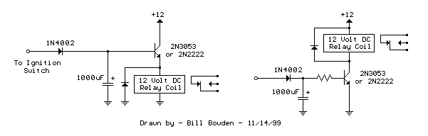
The two circuits di atas illustrate opening a relay contact a short time after the ignition or light switch is turned off. The capacitor is charged and the relay is closed when the voltage at the diode anode rises...
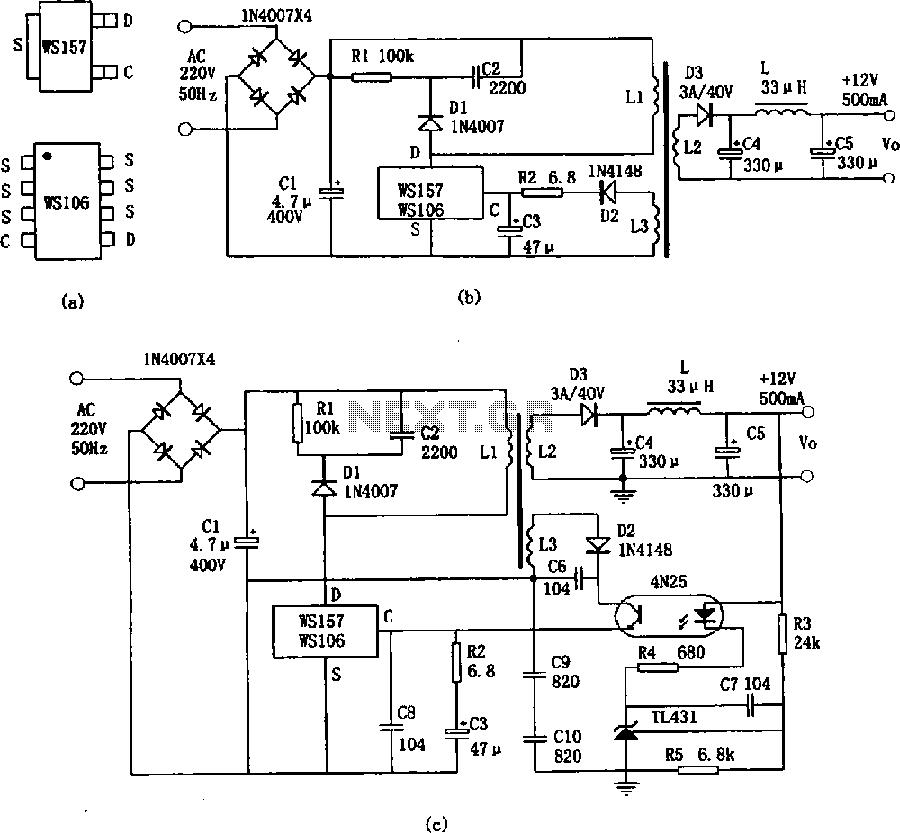
The WS157 or WS106 is a low-power miniature switching power supply that has been developed in recent years. It functions as a regulated switching power supply control device, featuring integrated internal control circuitry and power switches on a single...
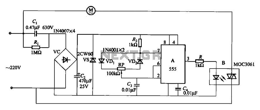
The circuit depicted in Figure 3-9 shares similarities with Figure 3-8, with the distinction that the zero-off MOC3061 type photoelectric coupler is directly connected to control the operation of the fan. The circuit utilizes the MOC3061, a phototransistor optoisolator, which...