
FM Radio Receiver for Battery Supply
The TDA7088T is a versatile bipolar integrated circuit designed specifically for mono FM radio applications, particularly in portable and pocket-sized devices. This IC is characterized by its low power consumption and compact design, making it suitable for battery-operated devices. The circuit typically includes an FM demodulator, audio amplifier, and necessary filtering components to ensure clear sound output.
In a typical application circuit, the TDA7088T is connected to an antenna to receive FM signals. The incoming radio frequency (RF) signals are processed by the internal demodulator, which converts them into audio frequency (AF) signals. These AF signals are then amplified using the integrated audio amplifier section of the IC. Additional components such as resistors, capacitors, and inductors may be used for tuning, filtering, and stability purposes in the circuit.
The circuit diagram for the TDA7088T will illustrate connections to the power supply, antenna input, and audio output. It may also include details on external components required for optimal performance, such as tuning capacitors for frequency selection and bypass capacitors for power supply decoupling. Overall, the TDA7088T is an efficient solution for creating compact and portable FM radio receivers.The TDA7088T can be used in mono portable and pocket radios. This is a bipolar integrated circuit. Here`s one of the application circuit diagram: When a. 🔗 External reference
Related Circuits
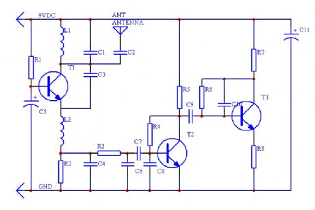
This is a simple RF receiver primarily designed for low-distance digital radio receiver applications. The analog output of this circuit should be connected to a Schmitt-trigger signal conditioning circuit with an appropriate capacitor value (from the collector of T3)....
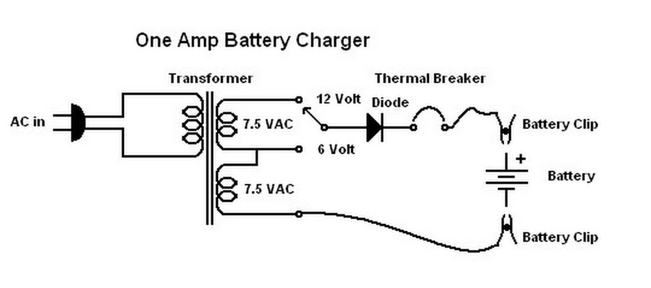
When this battery charger was purchased in 1970, it was not anticipated that it would still be relevant today. At that time, the owner had an old car with a weak battery that struggled to start in cold weather,...
Mobile phone chargers available in the market are quite expensive. The circuit presented here serves as a low-cost alternative to charge mobile telephones or battery packs with a rating of 7.2 volts. The proposed circuit design utilizes a straightforward approach to...
The transformer has a 240V primary and has a secondary rated 24V at 2A. The bridge rectifier contains 4 diodes, their current rating needs to be high with respect to the transformers output current; if not the current may...
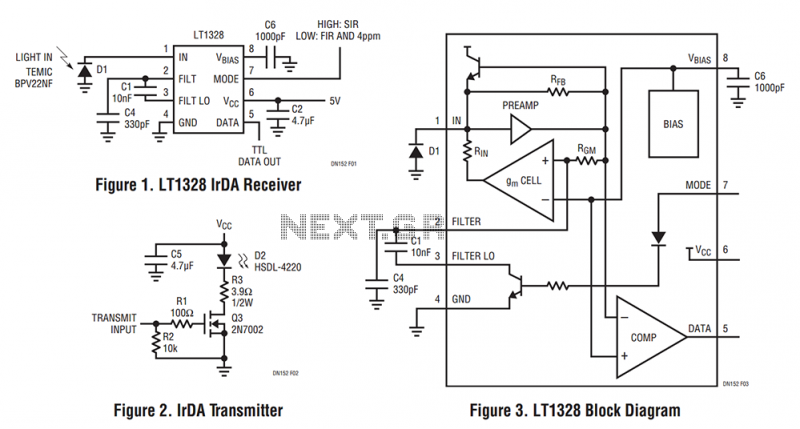
The LT1328, in the MS8 and SO-8 packages, contains all the necessary circuitry to convert current pulses from an external photodiode to a digital TTL output while rejecting unwanted lower frequency interference. The LT1328 plus five external components is...
As shown in the generator start battery automatic monitor circuit diagram. The generator start battery automatic monitor circuit is designed to oversee the battery's status during generator operation. This circuit ensures that the battery remains charged and functional, preventing premature...