
mobile phone battery charger circuit

The proposed circuit design utilizes a straightforward approach to provide an efficient and economical solution for charging mobile devices. It typically incorporates a transformer, a rectifier, a voltage regulator, and necessary protection components to ensure safe operation.
The transformer is responsible for stepping down the AC mains voltage to a lower AC voltage suitable for charging. The output of the transformer is then fed into a rectifier, which converts the alternating current (AC) to direct current (DC). A full-wave bridge rectifier is commonly used for this purpose, allowing for efficient conversion and minimizing ripple voltage.
Following rectification, the DC output may still be higher than the required 7.2 volts. Therefore, a voltage regulator is implemented to stabilize the output voltage at the desired level. Linear voltage regulators, such as the LM317, can be used for adjustable output, while fixed voltage regulators can provide a constant output voltage suitable for charging.
In addition to these main components, inclusion of capacitors at the output of the rectifier and regulator is essential for smoothing the voltage and filtering out any residual ripple. Furthermore, diodes may be used for reverse polarity protection to prevent damage to the connected device in case of incorrect connections.
Safety features, such as fuses or circuit breakers, should also be considered in the design to protect against overcurrent conditions. Overall, this circuit design offers a practical and cost-effective solution for charging mobile devices, making it accessible for users seeking affordable alternatives to commercial chargers.Mobile phone chargers available in the market are quite expensive. The circuit presented here comes as a low-cost alternative to charge mobile telephones/battery packs with a rating of 7.2 volts.. 🔗 External reference
Related Circuits
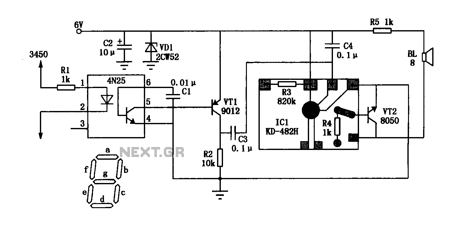
The General Dynamic LED digital clock lacks a timekeeping function, but by adding a simple circuit, it can incorporate this feature. The integrated circuit (IC) includes a programmable mute function, which is inactive from 23:00 to 5:00 to avoid...
This electronic clock comprises the LM8365 and the LDD640R displays. The LM8365 can show the hour/minute and month/day. Users can set two alarm outputs, AD1 and AD2, by pressing either the 12h or 24h button. The operating voltage range...
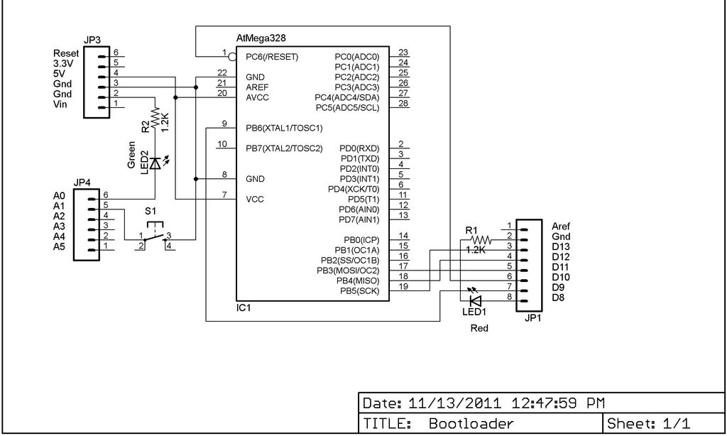
This Lazy Old Geek is also an Arduino enthusiast. One of the common microcontrollers used by Arduinos is the Atmega328 chip. To utilize Arduino software, the Atmega must be equipped with bootloader software. There is a notable difference between...
A 2 x 18W Hi-Fi Stereo Power Amplifier is designed using two TDA2030 integrated circuits (ICs). This amplifier features excellent input sensitivity, low distortion levels, stable operation, and comprehensive protection against overloads and output short circuits. It can serve...
The ping of the cymbals, crack of the snare drum, thonk of the bass - none of these comes through on my low-budget speakers. Sometimes they sound so fuzzy I want to hide behind the couch until it’s over....
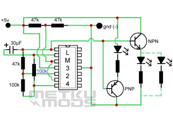
This circuit creates an LED color fade effect. As indicated by the name, the light intensity of the LEDs in this circuit transitions from high intensity to low intensity and eventually turns off. A 30 µF capacitor and a...