
fm receiver based on cxa1019
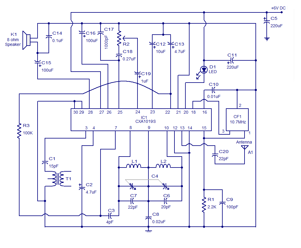
The FM receiver circuit utilizing the CXA1019 IC is designed to deliver high-quality audio reception for FM broadcasts. The CXA1019 integrates multiple functions into a single chip, simplifying the design and reducing the overall component count. Key components within the CXA1019 include:
1. **RF Amplifier**: This stage enhances the weak radio frequency signals received by the antenna, ensuring better sensitivity and selectivity.
2. **Mixer**: The mixer combines the incoming RF signal with a locally generated oscillator signal to produce an intermediate frequency (IF) signal, which is easier to process.
3. **Oscillator**: The oscillator generates a stable frequency signal that is essential for the mixing process and tuning the receiver to the desired frequency.
4. **Amplifier**: The amplifier boosts the IF signal to a level suitable for further processing, ensuring optimal signal strength.
5. **Quadrature Detection Circuit**: This circuit demodulates the FM signal, converting it back into an audio format that can be amplified and sent to the speaker.
6. **Tuning LED Driver**: This feature provides visual feedback to the user, indicating the tuning status of the receiver.
7. **Electronic Volume Control**: This allows for precise adjustments to the audio output level without the need for mechanical potentiometers.
8. **FM Detector**: The FM detector extracts the audio signal from the modulated carrier wave, allowing the audio to be played through the connected speaker.
The circuit is designed to operate within a power supply range of 3 to 7 V DC, making it suitable for battery-powered applications. The ability to drive an 8-ohm speaker allows for direct connection to standard audio output devices, making this circuit ideal for portable FM receiver projects. Overall, the CXA1019-based FM receiver circuit is a versatile and efficient solution for high-quality FM audio reception.Its a high quality FM receiver circuit based on IC CXA1019. CXA1019 is a monolithic silicon bipolar radio FM / AM receiver IC for Sony. Built in circuitry within the CXA1019 includes RF amplifier, mixer, oscillator, amplifier, quadrature detection circuit, tuning LED driver control electronic volume, FM detector, etc. HF section is only used in t his circuit. The IC can be powered by a figure between 3 to 7 V DC and can lead to an 8 ohm speaker 🔗 External reference
Related Circuits
This circuit combines two or more audio channels into a single channel (for example, converting stereo to mono). It is designed to handle any number of channels while consuming minimal power. The schematic illustrates two input channels, but additional...
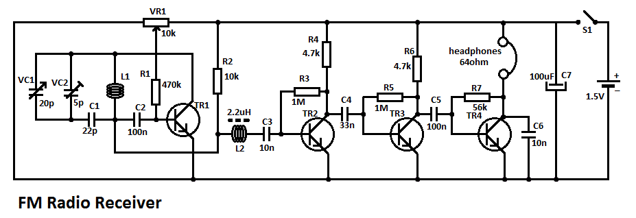
This simple FM radio receiver circuit consists of a regenerative RF stage, TR1, followed by a two or three-stage audio amplifier comprising TR2 to TR4. In some areas... This circuit is designed to receive FM radio signals, utilizing a regenerative...
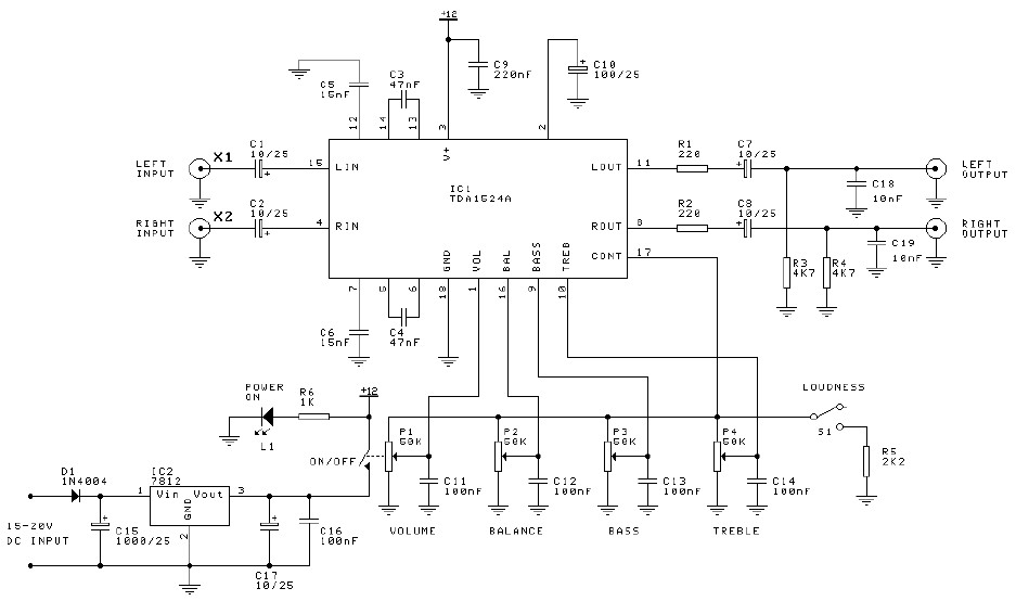
Preamplifier and tone control circuit based on the TDA1524A. The tone control circuit module is included in this preamplifier circuit, allowing for direct connection of the output channels to a stereo power audio amplifier circuit. This RIAA stereo preamplifier...
This is a general purpose serial port infrared receiver. With the help of appropriate software, you can control different functions of your PC from a distance. For example, you can control your home cinema settings (volume, play, pause, stop,...
This set of two circuits forms the basis for a simple light wave transmitter. A laser beam is modulated and directed towards a receiver that demodulates the signal and presents the information, such as voice or data. The assembly...
The AmpLoadPull project demonstrates the utilization of the AmpLoadPull and LoadPullSetup components in Advanced Design System (ADS). These components are part of the ADS behavioral model suite located within the System - Data Models palette. The schematic "circuit_level_amplifier_1_tone.dsn" represents...
Warning: include(partials/cookie-banner.php): Failed to open stream: Permission denied in /var/www/html/nextgr/view-circuit.php on line 713
Warning: include(): Failed opening 'partials/cookie-banner.php' for inclusion (include_path='.:/usr/share/php') in /var/www/html/nextgr/view-circuit.php on line 713