
stereo to mono converter based on fet

The audio mixing circuit is an essential component in various audio applications, enabling the integration of multiple audio sources into a unified output. The basic configuration typically consists of resistive mixing, where each input channel is connected to a summing point through resistors. This method ensures that the audio signals from different sources can be blended without significant distortion or loss of quality.
The circuit can be constructed using operational amplifiers (op-amps) to achieve a high degree of fidelity. In this case, each input channel is fed into an inverting summing amplifier configuration, where the op-amp combines the signals. The resistors connected to each input determine the weight of each channel in the final output, allowing for precise control over the mix.
Power consumption is minimal due to the low-voltage operation of the op-amps, making the circuit suitable for battery-powered devices or applications where energy efficiency is paramount. The layout of the circuit should ensure that the input sections are easily accessible for modifications, enabling the user to add or remove channels as needed.
For practical implementation, it is advisable to include decoupling capacitors near the power supply pins of the op-amps to filter out any noise that may affect the audio quality. Additionally, output coupling capacitors can be used to block any DC offset, ensuring that only the AC audio signal is delivered to the next stage of the audio system.
Overall, this circuit serves as a versatile tool for audio processing, allowing for flexible channel mixing while maintaining a low power profile.This simple circuit mixes two or more channels into one channel (e.g. stereo into mono). The circuit can mix as many or as few channels as you like and consume very little power. The mixer is shown with two inputs, but you can add as many as you want by just duplicating the ""input sections"" which are clearly visible on the schematic.. 🔗 External reference
Related Circuits
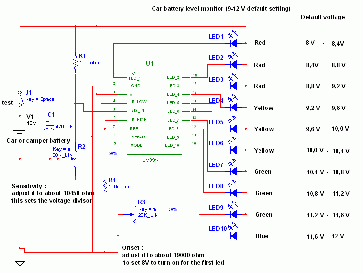
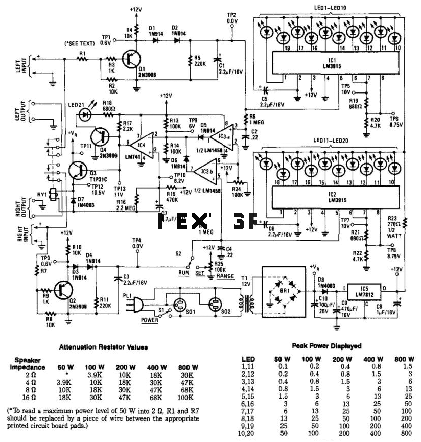
This circuit utilizes the widely available LM3914 integrated circuit (IC), which is straightforward to operate and does not require external voltage regulators due to its built-in voltage regulation capabilities. It can be powered from various sources. When the test...
R1 2.2K 1/4W Resistor, R2 27K 1/4W Resistor, R3, R4 2.2K 1/2W Trimmers (Cermet or Carbon), R5 100R 1/4W Resistor, R6 1K 1/4W Resistor, R7, R8 330R 1/4W Resistors, C1 22 µF 25V Electrolytic Capacitor, C2 47pF 63V Polystyrene...
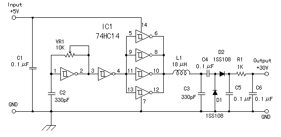
I made the power supply which makes about +30V with +5V power supply. The direct current is changed into the alternating current by the oscillator which used the schmitt trigger inverter which has the hysteresis characteristic and the resonance...

The pressure transmitter circuit data acquisition system utilizes the 1B31, an 18-bit A/D converter (AD1170), and an MCS-51 microcontroller. The configuration, as depicted in the accompanying diagram, features a full-scale output voltage of 10 mV from the pressure transmitter...
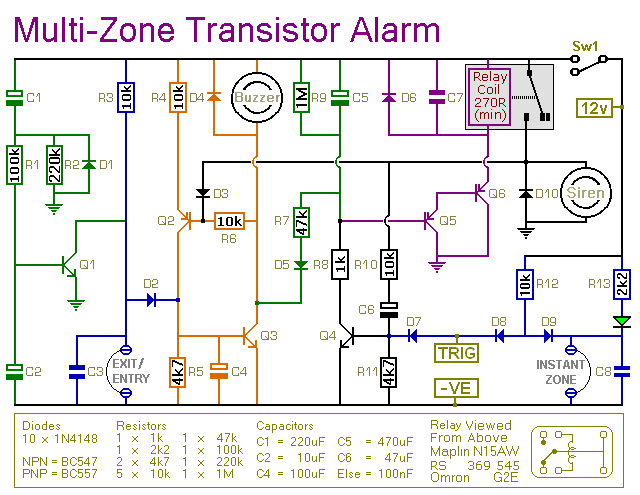
This transistor-based alarm system incorporates automatic exit and entry delays, along with a timed bell cut-off and system reset functionality. In addition to the exit/entry zone, the fundamental alarm board includes one instant zone, which is sufficient for many...
This circuit is designed to measure the audio power output of an amplifier connected to a speaker. Relay RY1 is activated when excess power is delivered to the speaker. The circuit includes two channels for stereo applications. Resistors R1,...