
FM Receiver circuit
More: Via a feedback loop, the phase detector continuously adjusts the frequency of the oscillator in the FD-1A in such a way that there is a 90 degrees phase difference between the FD-1A oscillator and the external oscillator (T2/T3). Since the received signal is frequency-modulated, the output of the phase detector is an exact replica of that modulation. Alignment of the receiver involves the trim potentiometers P1 and P2 in the IF amplifier, besides P3 in the stereo decoder. P1 is initially turned completely counterclockwise and P2 completely clockwise. Some stations can now be heard. If P1 is turned clockwise, the audio volume increases but at a certain point distortion will occur. The right setting of the pot is just before the onset of distortion. Checkpoint 10 (or H) is then about 0.5 Volts positive with respect to checkpoint 9 (also marked J). P2 is now turned counter-clockwise. The signal-to-noise level improves but at a certain setting of the pot a crackling kind of distortion sets in. The right setting is again: just before the onset of distortion. P2 adjusts the bandwidth of the IF amplifier. P1 presents a DC bias voltage to the AFC diode in the FD-1A, this should ensure that the diode works in the linear part of its range. Alignment should be performed during reception of a stereo broadcast. The alignment should be repeated a few times since there is some interaction between the two trimpots. Once aligned the circuit is very stable. The room is also rather heavily shielded by the surrounding houses, resulting in low field strengths of most transmitters - in particular my favorite, Radio 4. For initial tests, two pieces of wire were used as an aerial but this was not a success. Although the tuner received stations at virtually every setting of the dial, stereo broadcasts of the weaker transmitters were plagued with noise and the sound quality was poor. Much better results are obtained with an ancient dipole antenna made from (300 Ohm) twinlead. Optimal results are obtained not with a horizontal but with a vertical orientation of the dipole.
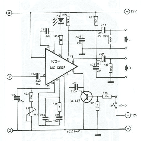
The described circuit is a sophisticated FM receiver utilizing the Valvo FD-1A module, TBA120 integrated circuit, and MC1310 components, employing a phase-locked loop (PLL) for effective signal demodulation. The architecture includes an RF amplifier, oscillator, and mixer stages, implemented using BF324 and BF451 transistors. The tuning mechanism is facilitated by four variable capacitors (varicaps) designated as BB104, allowing for fine frequency adjustments.
The receiver's intermediate frequency (IF) processing begins with a 30 dB gain stage, utilizing a single transistor (T1). The TBA120 provides an additional gain stage, enhancing the overall sensitivity of the receiver. The phase detector, integral to the TBA120, compares the 10.7 MHz IF signal with an externally generated 10.7 MHz signal from a dedicated oscillator constructed with transistors T2 and T3. A ceramic filter (SFE10.7MA) is employed in place of a traditional crystal, which aids in maintaining signal integrity.
A feedback loop from the phase detector continuously adjusts the FD-1A oscillator frequency to maintain a 90-degree phase difference with the external oscillator. This mechanism ensures that the output of the phase detector accurately reflects the frequency modulation of the incoming signal. The alignment process of the receiver involves the careful adjustment of trim potentiometers P1 and P2, which control the gain and bandwidth of the IF amplifier, respectively.
P1 is used to set a DC bias voltage to the AFC diode within the FD-1A, ensuring optimal performance in its linear range. The alignment procedure is critical and may require multiple iterations due to the interdependence of the adjustments. The circuit exhibits stability once properly aligned, although environmental factors such as shielding from surrounding structures can impact performance, particularly in areas with low signal strengths.
Initial testing with a simple wire aerial yielded suboptimal results, highlighting the importance of using a more effective antenna configuration. An ancient dipole antenna, constructed from 300 Ohm twinlead and oriented vertically, significantly improved reception quality, particularly for weaker stereo broadcasts. Proper antenna selection and orientation are essential for maximizing the performance of this FM receiver circuit.Based on Valvo FD-1A module, TBA120, and MC1310. Operation of the receiver is based on the phase locked loop principle. The FD-1A contains an RF amplifier, oscillator and mixer (made with BF324, BF451 and BF324 transistors, respectively). Tuning is performed with four varicaps (BB104). There is an additional AFC diode which allows voltage control of the oscillator frequency over a relatively narrow range (see Fig.2).
The IF amplifier starts with a 30 dB gain stage using a single transistor (T1 in fig.3). Additional IF gain is provided by the TBA120. A phase detector (which is also part of the TBA 120) compares the 10.7 MHz IF signal with the signal of a 10.7 MHz oscillator built with two RF transistors (T2 and T3 in Fig.3) and using a ceramic filter (SFE10.7MA) in stead of a 10.7 MHz crystal. Via a feedback loop, the phase detector continuously adjusts the frequency of the oscillator in the FD-1A in such a way that there is 90 degrees phase difference between the FD-1A oscillator and the external oscillator (T2/T3). Since the received signal is frequency-modulated, the output of the phase detector is an exact replica of that modulation.
Alignment of the receiver involves the trim potentiometers P1 and P2 in the IF amplifier, besides P3 in the stereo decoder. P1 is initially turned completely counterclockwise and P2 completely clockwise. Some stations can now be heard. If P1 is turned clockwise, the audio volume increases but at a certain point distortion will occur. The right setting of the pot is just before the onset of distortion. Checkpoint 10 (or H) is then about 0.5 Volts positive with respect to checkpoint 9 (also marked J, see Fig.3).
P2 is now turned counter-clockwise. The signal-to-noise level improves but at a certain setting of the pot a crackling” kind of distortion sets in. The right setting is again: just before the onset of distortion. P2 adjusts the bandwith of the IF amplifier. P1 presents a DC bias voltage to the AFC diode in the FD-1A, this should ensure that the diode works in the linear part of its range.
Alignment should be performed during reception of a stereo broadcast. The alignment should be repeated a few times since there is some interaction between the two trimpots. Once aligned the circuit is very stable. The room is also rather heavily shielded by the surrounding houses, resulting in low field strengths of most transmitters - in particular my favorite, Radio 4.
For initial tests, I used two pieces of wire as an aerial but this was not a success. Although the tuner received stations at virtually every setting of the dial, stereo broadcasts of the weaker transmitters were plagued with noise and the sound quality was poor. Much better results are obtained with an ancient dipole antenna made from (300 Ohm) twinlead. Optimal results are obtained not with a horizontal but with a vertical orientation of the dipole. 🔗 External reference
Related Circuits

A simple audio amplifier with a 10 Vpp output designed for use with the AD633 ring modulation chip. The datasheet for the chip is available, and the circuit will utilize the XR2206 function generator IC for the modulation input....
Which switch mode power supply (SMPS) topology should one start with? Although the schematic of a full-bridge looks a bit complicated compared to push-pull and half-bridge designs, sticking straight to a full-bridge topology or its smaller version, the half-bridge,...
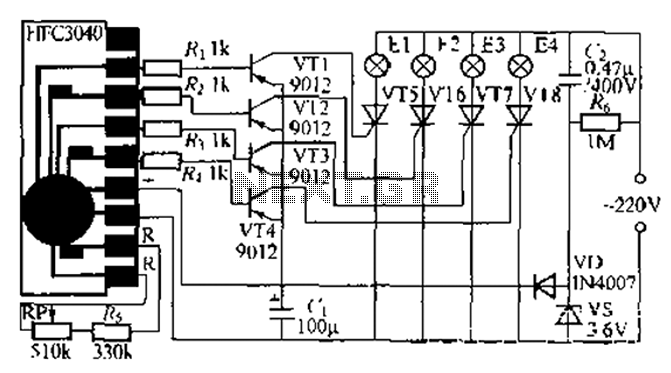
The circuit utilizes a four-way slowly dimming LED driver integrated with iU shoe production and a Qis four flashing lights string controller. The C3484 manifold is specifically designed to operate Ji lights with four lights that flash and slowly...

Most thefts occur after midnight when individuals enter the second phase of sleep known as 'paradoxical sleep.' Here is an energy-saving circuit that causes... An energy-saving circuit designed for security applications can be particularly beneficial during the late-night hours when...
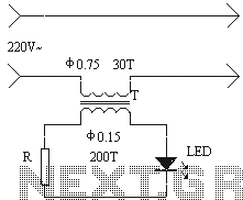
The installation of an electrical outlet in the refrigerator work light serves to enhance visibility of the refrigerator's interior while also improving the aesthetic appeal of the socket. The circuit is illustrated. Additionally, the circuit utilizes the secondary induced...
The Zener diode may not be providing sufficient current in its breakdown state to activate the transistor. Removing resistor R2 did not resolve the issue. The Zener's voltage selection could be too high, potentially preventing it from regulating the...