
Four flashing lights string circuit 2
The four-way slowly dimming LED driver circuit is particularly effective for applications requiring a gradual lighting effect. The integration with the Qis flashing lights string controller enhances the visual display, making it suitable for decorative lighting, mood lighting, or signaling applications. The design features a robust architecture that allows for seamless transitions between lighting states, achieved through precise control of the output phases.
The use of the C3484 chip ensures efficient operation, allowing for direct control of LEDs or crystal diodes. The half-wave rectifier and voltage regulator work in tandem to maintain a stable output, which is critical for consistent performance across varying load conditions. The sequential input of negative-going pulses to the outputs ensures that the lights operate in a coordinated manner, creating a dynamic lighting sequence.
The external transistors serve as amplifiers for the input signals, ensuring that the thyristors are triggered effectively. This design choice enhances the reliability of the circuit, as the transistors can handle higher currents than the input signals alone. The selection of thyristors rated for high voltage and current ensures that the circuit can handle the demands of multiple LEDs without risk of failure.
Adjustability is a key feature of the design, with the inclusion of the potentiometer (RP) allowing users to fine-tune the brightness and flow rate of the light string. This flexibility is particularly beneficial in applications where ambient lighting conditions may vary.
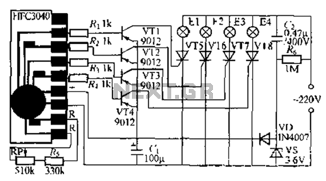
Overall, this circuit design combines functionality, efficiency, and aesthetic appeal, making it a versatile solution for various lighting applications. The careful selection of components and the thoughtful arrangement of the circuit elements contribute to its effectiveness and reliability in delivering a visually engaging lighting experience. Clever use of a four-way slowly dimming LED driver integrated iU shoe production and Qis four flashing lights string controller. Ten Electronics Co., Ltd. Wenzhou production HF C3484 manifold is dedicated to play Ji light with four lights flashing slowly fades the chip, which uses black soft paste package measuring 2mm 9 iimm. It is programmed to delete the case when asked, H1 output can directly drive a light-emitting diode or a crystal diode, each output phase difference of 90.
Flashing. VD, vs, C, C blink R. Group ring simple half-wave rectifier capacitor step-down voltage regulator circuit, power and energy output 3V left some DC voltage supply manifold HFC3-184 use electricity. Manifold four outputs Ql - Q4 sequentially input {fj negative-going pulses, by R. ~ R. By an external transistor VTl - VT4 trans to zoom into a positive pulse followed by a touch hair thyristor VT5-VT8, called road driving lights take E1-E2 E3- F: 4 - F: 3- F.2 - - order Di lit by slowly fades, as long as the four lights for proper arrangement in space can be formed of water-efficient results.
RR manifold connected between an electrical terminal is busy RP and resistance R, meet their external oscillation resistor, adjust the RP can change the resistance of the flow rate of the light string, table 8-1 for the size of its output resistance of a cycle time off line. VTI --VT1 are Wu Ding with 9012-type silicon PNPj shake tube requires p 100; VTo-VTS are available MCRIOO-S-type cut and other small plastic products unidirectional thyristor (IA, 600V).
Fl ~ E4 each lantern power not exceeding 1.. W is appropriate. RP wFj type using small synthetic carbon potentiometer, C, requires CIm-4. ov poly propylene [U container, several other devices without special requirements. Bong circuit/f debugger, power that can make normal L. In order to prevent the thyristor VT5-VTS can receive a T r small disturbance can make [Bu Chang may be at each gate electrode and the cathode of the thyristor in parallel and then ask one o OirLF ceramic dielectric container malfunctioned acridine excluded.
Related Circuits

Multi-output power supply circuit (MAX1902). This circuit illustrates the power supply configuration for a notebook computer motherboard, utilizing the MAX1902 chip for power control. It is designed to convert the battery's DC voltage into multiple DC voltage outputs. The multi-output...

When driving at night and approaching another vehicle, traffic regulations dictate that the distance between the two vehicles should be maintained. This is achieved by alternately activating and deactivating the high beams, while utilizing either the wide lights or...
This circuit is a wireless car alarm system constructed using two modules: a transmitter module and a receiver module. It operates on FM radio waves and is suitable for vehicles with a power supply of 6-12VDC. A voltage stabilizer...
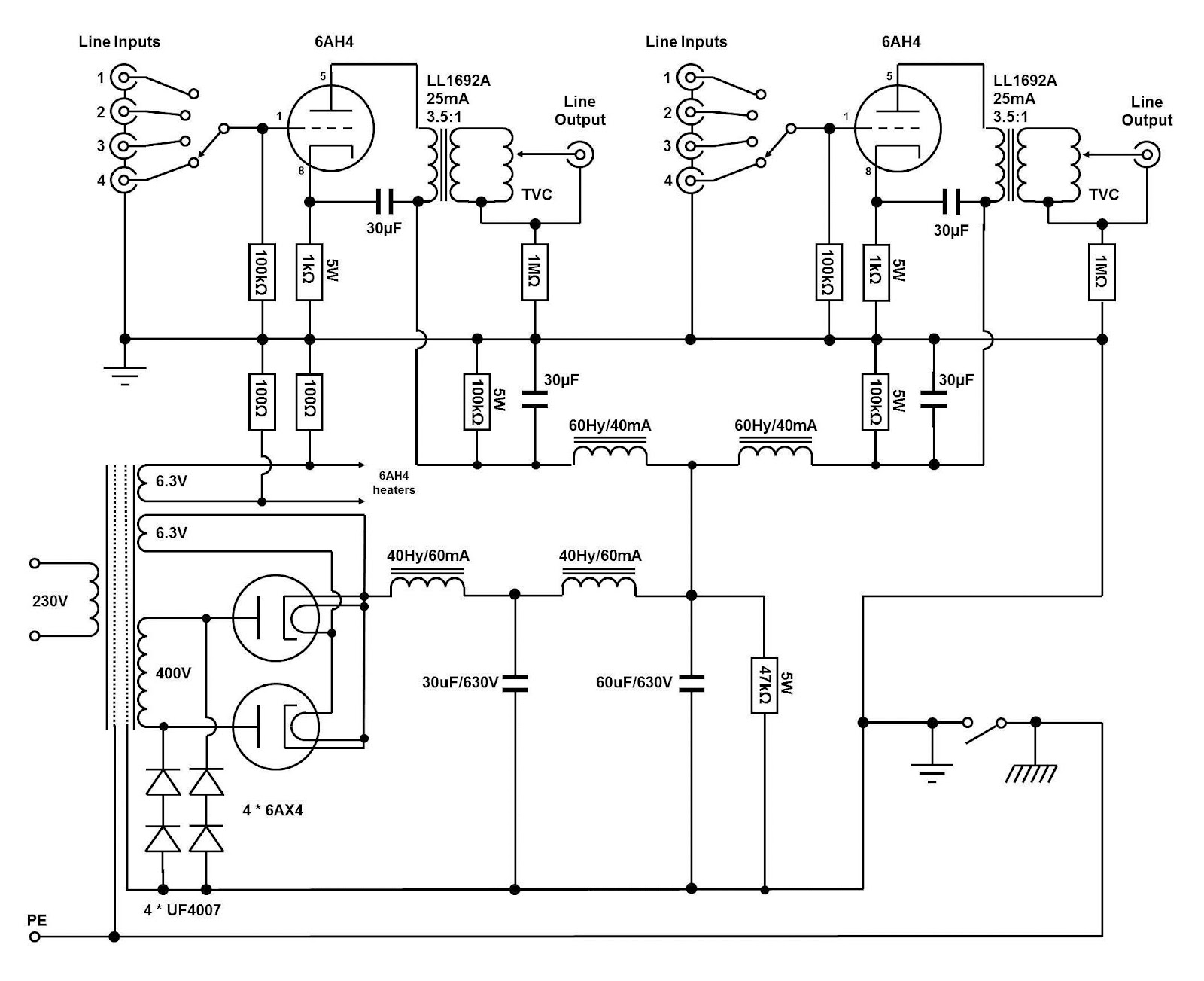
The circuit and assembly process of the line stage is presented in two separate articles. This linestage shares the same circuit as the two chassis version previously described. However, in this design, the power supply and preamplifier are housed...
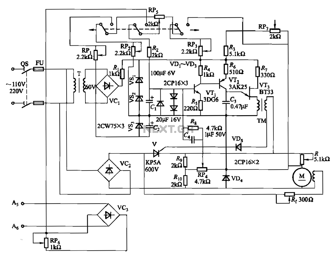
A 100W full-wave single-junction transistor trigger control circuit designed for constant or variable speed control of a wire feed motor. The input control signal consists of a voltage adjusted by the master potentiometer (RPs) and a feedback voltage from...
The circuit utilizes multiple integrated circuits to form an automatic lighting device that is activated by door and window sensors. It includes CD4093 digital integrated circuits, a relay, and a power supply circuit. The system typically remains closed when...