
Fm Stereo Transmitter Circuit
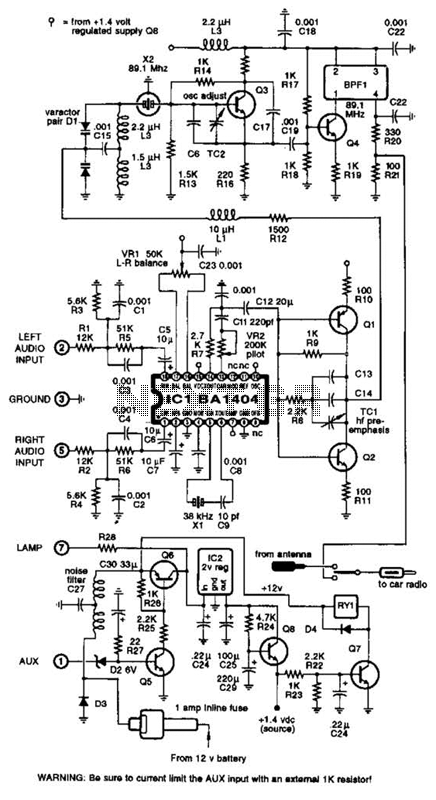
The BA1404 IC is designed for FM stereo broadcasting and is capable of generating a high-quality multiplexed audio signal. The pre-emphasis circuit, formed by the components CI, R3, R4, and C4, enhances the higher frequencies of the audio signal before transmission, which is crucial for improving the signal-to-noise ratio and ensuring better reception quality.
The transmitter's power supply is a single AA cell, providing a compact and portable solution for FM transmission. The use of L3 and L4 as the inductors in the circuit is critical for the tuning and stability of the oscillator. L3, with its three turns of #20 wire, is designed to provide a specific inductance value that is necessary for the desired operating frequency. The length of L3 is important as it can influence the inductance and thus the performance of the oscillator circuit.
L4, consisting of four turns of #20 wire, is similarly designed to contribute to the circuit's tuning characteristics. The specific spacing on the Me drill bit is essential to achieve the required inductance and to minimize unwanted capacitance that can affect the circuit's performance.
For applications requiring monophonic audio transmission, the design can be simplified by omitting C5 and the components associated with the 38-kHz oscillator. This modification allows the circuit to operate in a simpler mode, which is beneficial in scenarios where stereo sound is not necessary, thus reducing component count and complexity while maintaining functionality.
Overall, this circuit design utilizing the BA1404 IC is suitable for various FM transmission applications, offering flexibility in operation modes and ease of implementation. A BA1404 IC is used to generate a complete FM MPX signal. The chip contains all of the necessary circuitry. CI and R3, and R4 and C4 provide pre-emphasis. The transmitter runs on a single AA cell. L3 is 3 turns of #20 wire on a Ke drill (for a form). L3 is long. L4 is 4 turns #20 wire on `Me drill bit, spaced to %. If monophonic operation is wanted, omit C5 and the 38-kHz oscillator components. 🔗 External reference
Related Circuits
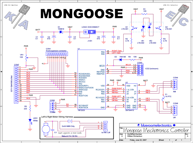
Control the state (on/off) and direction of two linear actuators that are essentially DC motors. The linear actuators operate at 12VDC and draw 10 amps of current at full load. A 25A external power supply has been purchased, as...
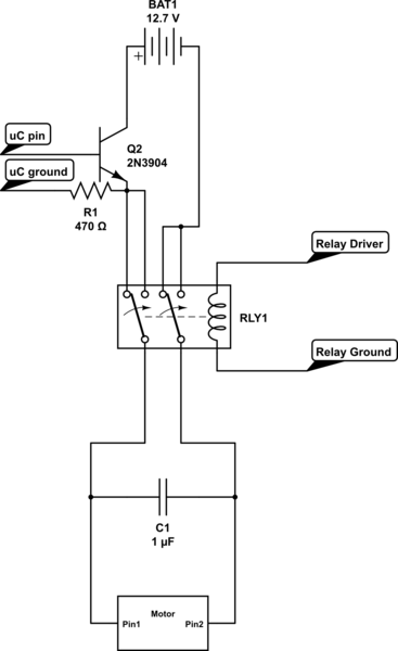
Is there a circuit that can be used to make a DC motor move randomly backward and forward, stop for a period, and then start again? Any assistance and ideas would be greatly appreciated. Research how to wire up...
This is a very simple crystal receiver circuit for short wave band and can be used with headphones. The described circuit is a basic crystal receiver designed to operate within the shortwave frequency band. The primary components of this circuit...
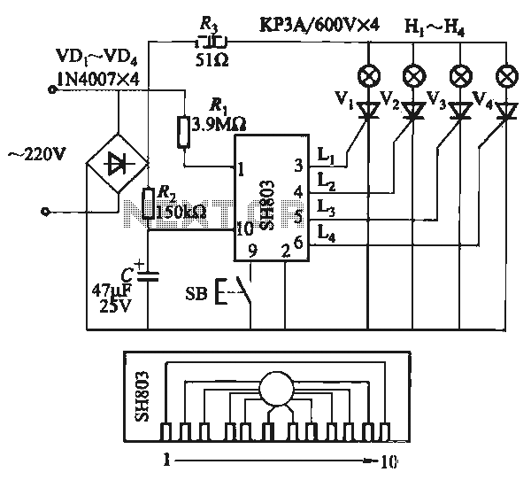
The circuit utilizes the SH803 flash IC, which can store eight different programs and offers various dimming options and light speed adjustments. A button is provided to trigger the control terminal SB on the 9-pin connector for program selection,...
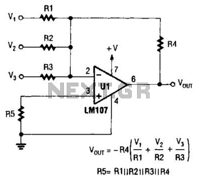
The output of Ul is the sum of Vv, multiplied by the ratio of Rx to Rv, RJRV, and respectively. Resistors R1, R2, and R3 are selected as required for individual gains. Additionally, R4 influences the gain of all...
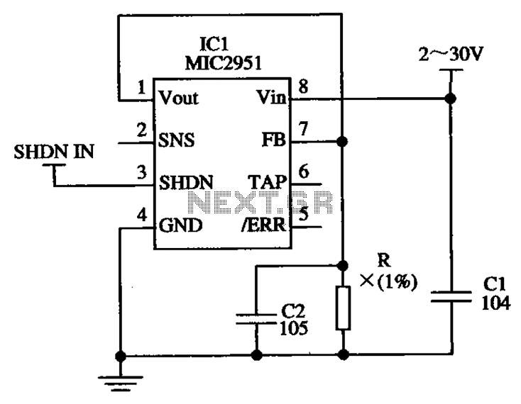
The circuit illustrated in the figure utilizes the low-drift current source circuit MIC2951, which is designed to provide specific output current values. The MIC2951 is a precision voltage regulator that can also be configured to function as a low-drift current...
Warning: include(partials/cookie-banner.php): Failed to open stream: Permission denied in /var/www/html/nextgr/view-circuit.php on line 713
Warning: include(): Failed opening 'partials/cookie-banner.php' for inclusion (include_path='.:/usr/share/php') in /var/www/html/nextgr/view-circuit.php on line 713