
random motor circuit
To create a circuit that enables a DC motor to move in a random pattern, alternate between moving forward and backward, and pause at intervals, a microcontroller such as a PIC (Peripheral Interface Controller) can be employed. The circuit design will incorporate an H-bridge configuration, which allows for bidirectional control of the motor. The H-bridge can be implemented using an integrated circuit like the SN75410, which simplifies the design by consolidating multiple discrete components into a single package.
Powering the circuit requires a voltage regulator, such as the LM7805, to ensure that the microcontroller and other components receive a stable voltage supply. The LM7805 can convert a higher input voltage down to a regulated 5V output, suitable for most microcontrollers. Bypass capacitors should be placed between the V+ and ground to filter out noise and stabilize the voltage levels, enhancing the reliability of the circuit.
The microcontroller can be programmed to control the motor's direction and timing using digital output pins. The internal oscillator of the microcontroller can be utilized for timing functions, or an external oscillator can be connected if higher precision is required. The program logic can include random delays and direction changes, allowing for the desired movement pattern.
In summary, the circuit will consist of a microcontroller, an H-bridge IC, a voltage regulator, and necessary bypass capacitors. Proper wiring and programming will enable the DC motor to operate as specified, moving randomly and pausing at intervals.Does anyone know what circuit i can use to make a dc motor randomly move backward and forward, stop for a period of time and then start again Any help and ideas will be much apreciated. Google and read about how to wire up PICs. In the simplest sense, it involves wiring up power through a simple voltage regulator IC, some bypass capacitors betwee
n V+ and ground to stabilize the voltage, and wiring up the oscillator. A lot of microcontrollers now also have an internal oscillator so if that is good enough you don`t even need to wire it up an oscillator (just power). How much easier can it get Google around for SIMPLE PIC circuits that do different things and compare the similarities between them.
THat`s what is needed to wire up in the most basic form. THere are some things that are too vast, take too many words and unwarranted to take you step-by-step through them on a forum. Come back after you`ve done some of the reading and ask specific questions that will be easier for us to answer, and for you to understand the answers to.
If I waste my time spitting out a huge chunk of text, you still probably wouldn`t understand it because that`s just the way it is. We aren`t exactly here to hold your hand (and your last post irked me quite a bit in the "exact" nature of the request and wording because it seems to indicate a complete lack of effort on your part).
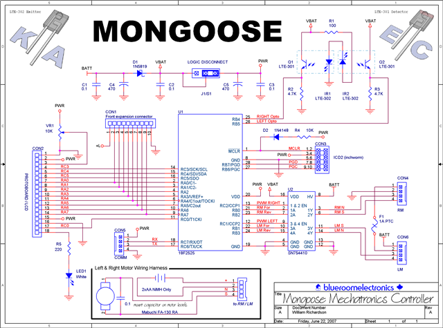
blueroom, I think it`s just funny the way your little avatar seems to look at the schematic for the mongoose. (Like are you sure you want to do this Or I really don`t think he knows what he`s getting himself into.
) TO simplify BLueroom`s schematic, you can probably chop off everything to the left and top of the PIC in the middle, leaving only the stuff to it`s right, and the motor part to the bottom. In his schematic, he used an H-bridge IC rather than one of discrete components (The SN75410). No regulator is in the circuit for the PIC so one should be added. A starting place to look at is how to use the LM7805. It`s very simple, you should have no problem understanding how it`s used if you take a glance at the datasheet (or the datasheet of any other linear regulator).
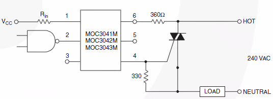
I have no idea what those optocouplers are for on the top-right of the schematic so you can ignore those too. Notice the H-bridge has uses the "raw" voltage (or a different voltage supply) from the PIC. The PIC uses a voltage that has been cleaned up by a regulator (not shown) 🔗 External reference
Related Circuits
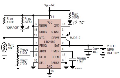
The LTC4060 integrated circuit can be utilized to create a straightforward smart NiMH battery charger electronic project. This charger circuit functions as a complete fast charging system for NiMH or NiCd batteries. It requires only a few external components...
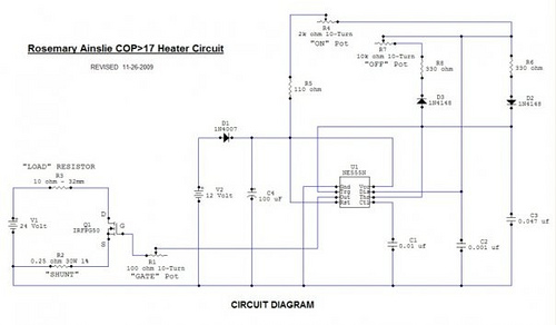
Recently, the Overunity and Energetics online forums, which serve as significant platforms for members of the Open Source and Free Energy communities, have been discussing a remarkable phenomenon known as the Rosemary Ainslie Circuit. This circuit is named after...
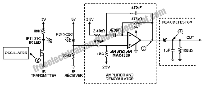
The following circuit illustrates an Infrared Proximity Sensor Circuit Diagram. This circuit is based on the MAX4230 integrated circuit. Features include a 10 kHz oscillator. The Infrared Proximity Sensor Circuit utilizing the MAX4230 integrated circuit is designed to detect the...
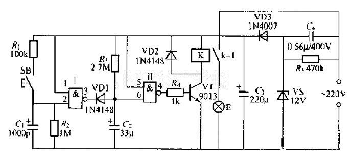
A 2-input NAND gate integrated circuit is used in the fabrication of a digital delay lamp circuit. This circuit is energized by a simple capacitive voltage rectifier, which operates by crossing the half line. The output terminal indicates the...
The primary components of this doorbell circuit include two NE555 timer integrated circuits (ICs). When the switch S1 is pressed momentarily, the loudspeaker emits a bell tone for the duration determined by the time period of the monostable multivibrator...
Switch 50V AC voltage. The maximum current drained will be 5A, with a frequency of 50Hz. The switching speed is not critical and can be slow, which is acceptable for the application. Initially, a solid-state relay (SSR) was considered...