
FM Transmission and Reception

The Phasitron tube's operation is critical for the modulation process in the FM transmitter. By achieving wide phase deviations, it effectively modulates the signal for transmission. The complexity of the tube's design allows for precise control over the electron flow and phase modulation. The deflection system's arrangement is crucial for ensuring that the electron disk maintains its intended shape, which directly impacts the quality of the transmitted signal. The careful design of the deflector grids and the application of RF voltages ensure that the modulation process is both efficient and effective, leading to enhanced transmission capabilities in the latest FM transmitters from General Electric. The integration of the Phasitron tube into the overall transmitter design exemplifies advanced engineering practices in the field of frequency modulation technology.The original f-m transmitters manufactured by the General Electric Company were the direct f-m type employing the regular electronic automatic frequency control system similar to that discussed in connection with the CBS transmitter. The f-m multiplication system in these original transmitters employed two triplers for a total frequency multiplica
tion of 9. In the new f-m transmitters the General Electric Company employs a completely different system. The new system is one of indirect f. m. where p. m. is the initial type of modulation. By using the proper audio frequency correction network the p-m signal is made equivalent to an f-m signal. The method of obtaining the initial amount of phase deviation is new. In these transmitters the famous Phasitron tube is employed as the modulator and the operation of the transmitter is based upon this tube.
Before we analyze the complete exciter and modulator system, let us first study the Phasitron tube and see how it works. The Phasitron tube enables us to obtain wide phase deviations, equivalent to a peak frequency deviation of about 175 cycles, from a crystal controlled source of about 200 kc.
The tube itself is quite a complicated structure so far as regular electron tubes are concerned. It more nearly belongs to the class of the cathode-ray tube than to any other type, although its size is comparatively small. A cutaway pictorial view of the Phasitron tube is shown in Fig. 4-13, while Fig. 4-19 provides a more technical cutaway view of the functioning elements together with a simplified diagram of the circuit elements to which it is wired.
In Fig. 4-19 all the parts shown are definite physical parts, except the so-called electron disk which is formed by a constant stream of electrons emanating from the cathode and focused on anode No. 1. Figure 4-19. Sketch of the functioning elements of the Phasitron tube and a simplified schematic diagram of the circuits to which they are connected.
Above and below the electron disk is the deflection system. The deflector grids consist of 36 wires every third one being connected, making three grids each having 12 wires. The voltages indicated in this and the next figure are typical of the slightly different operating conditions.
The heater voltage is at 6. 3 volts. When typical operating voltages (such as those indicated in Figs. 4-19 or 4-20) are applied to the tube, electrons begin to flow away from the cathode toward the two anodes. Without any external r-f voltage applied to the tube, the focusing electrodes regulate the electrons flowing away from the cathode so that they flow in a radial fashion and are concentrated into a thin electron disk, the shape of a flat plate.
Above and below this disk is a deflection system. Above the electron disk is the so-called neutral plane of the deflector system, and below the disk are the deflector grids. There are 36 deflector wires, so arranged that every third wire is connected together, making 3 grids with 12 connected wires in each.
All the deflector grids and the neutral grid have d-c potentials applied. The deflector grids are, however, excited by an additional r-f voltage while the neutral grid is not. Therefore the neutral deflector (referred to as the neutral plane) remains as a source of reference potential for the other deflector grids.
The r-f voltage is a 3-phase voltage obtained from a crystal controlled source. This crystal voltage passes through a phase-splitting network making the r-f voltages applied to each deflector grid group 120` out of phase with each other. For correct operating procedure, the amount of r-f voltage should be approximately 35 volts rms as measured between each deflector grid and the neutral plane deflector.
These 3-phase voltages as applied to the deflector grids deflect the electron disk so that the outer edge of the disk takes on a sinusoidal shape as seen in Fig. 4-21. In other words, there now exist 🔗 External reference
Related Circuits
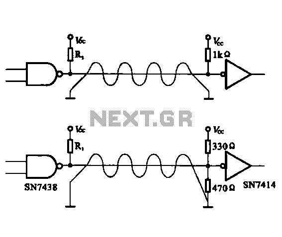
The circuit configuration for data signal output is designed to optimize transmission distance. It includes an output terminal connected to a pull-up resistor at the receiving end, which works in conjunction with two pull-up and pull-down resistors. The described circuit...
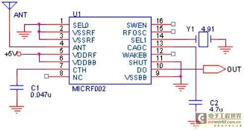
The project involves the development of a miniature transmitter suitable for implantation in a rat's body, capable of transmitting 416-bit data samples at a rate of 400 samples per second. It is designed to have a detection range of...
Traditionally, high-quality reception of Very Low Frequency (VLF) natural radio signals has required traveling to remote locations far from civilization to find an environment free of interference from artificial radio signals. Many attempts have been made to hike into...
The maximum coverage of the RSR232 serial port transport protocol is 10 meters, which poses significant challenges for remote transmission control. To address this issue, a design has been developed utilizing ultra-high frequency (above 300 MHz) for transmission. This...
The amplification of this circuit is approximately 12,000 times, with a bandwidth ranging from 0.5 to 14 MHz. The input resistance is 700 ohms, while the output resistance is 35 ohms (measured at 5 MHz). The output noise level...
This article demonstrates that enhancement mode GaN transistors facilitate substantial efficiency enhancements in resonant topologies and provides a practical example of wireless power transmission. Enhancement mode Gallium Nitride (GaN) transistors are semiconductor devices that have gained attention for their ability...