
Transmission distance of 5m or less circuit configuration

The described circuit configuration facilitates effective data signal transmission over extended distances. The primary function of the output terminal, connected to a pull-up resistor, is to ensure that the signal level is maintained high when not actively driven low by the transmitting device. This is crucial in digital communication systems to prevent floating states that can lead to erroneous data interpretation.
In this setup, the pull-up resistor at the receiving end serves to establish a defined logic level when the line is idle. When a data signal is transmitted, the pull-down resistor can be used to pull the line low, ensuring that the signal is clearly interpreted by the receiving circuit. The combination of these resistors helps to create a stable environment for the data signal, minimizing the effects of noise and signal degradation over longer distances.
To enhance the performance of this circuit, careful selection of resistor values is essential. The pull-up resistor should be chosen to provide sufficient current to maintain the high state while minimizing power consumption. The pull-down resistor should be selected to ensure that the signal can be driven low quickly, allowing for high-speed data transmission.
Additionally, the layout of the circuit should be optimized to reduce capacitance and inductive effects, which can adversely affect signal integrity. Proper grounding and shielding techniques may also be employed to further improve transmission quality, especially in electrically noisy environments.
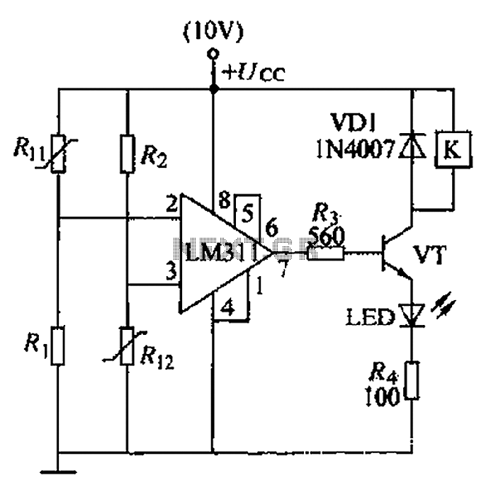
Overall, this configuration provides a reliable method for transmitting data signals over longer distances, ensuring that the information is accurately received and interpreted by the receiving device.Data signal output, transmission distance when Sm the following circuit configuration may be employed as shown, the main measure is the output terminal of the pull-up resistor at the receiving end of two pull-up and pull down resistors.
Related Circuits
The Johnson 275 watt and Kilowatt Matchboxes are often seen as exaggerated and unfairly criticized. They are neither exceptional tuners nor poorly designed. The main drawbacks include the fixed coupling link and the fact that they are balanced voltage...
The circuit operates as illustrated in Figure 5-2a. It includes an alarm switch (S). When switch S is pressed, relay K is activated, which closes two normally open contacts. This action triggers the alarm bells. The alarm continues to...

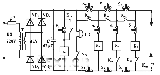
The SOS Alarm centralized control circuit is designed for use in calling a hospital bed and can also serve as an anti-theft alarm in multi-storey buildings, dormitories, warehouses, and similar locations. The circuit, as depicted in Figure 13-64, features...
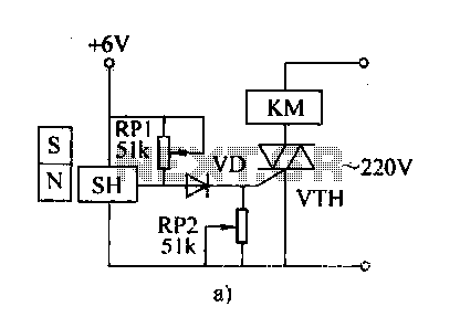
The automatic weapon features a magnetic switch circuit that is simple, reliable, has a low failure rate, and offers good versatility. It can be used for output performance or converted into mechanical displacement applications. The circuit diagram utilizes a...
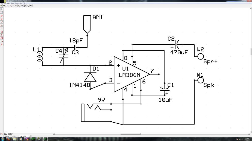
Initially, the individual has limited experience in electronics. They constructed a crystal radio circuit using components salvaged from a non-functional radio, including an LM386N audio amplifier. A crystal radio circuit is a simple radio receiver that operates without the need...
A boiler control circuit is designed to regulate the temperature of water in a hot water heating system. This circuit typically utilizes a comparator's comparison function to manage the heating equipment. The circuit includes a thermistor that forms a...