
FM Transmitter circuit
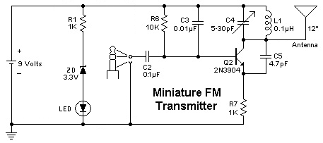
To implement the change from an electret microphone to a 3.5" audio jack, the following modifications should be considered. The electret microphone typically has two terminals: one for the audio signal and the other for power. The audio jack will require a similar configuration, where the tip of the jack carries the audio signal, and the sleeve provides a ground connection. It is essential to identify the corresponding pins on the audio jack to ensure proper connectivity.
1. **Wiring the Audio Jack**: The audio jack can be connected in place of the microphone. The signal pin from the microphone should be connected to the tip of the audio jack, while the ground pin should connect to the sleeve. If the original circuit includes any biasing resistors for the microphone, these may need to be adjusted or removed, as the audio jack will not require the same biasing.
2. **Adjusting Component Values**: Depending on the circuit design, it may be necessary to adjust component values such as resistors and capacitors that were tuned for the microphone's characteristics. The input impedance of the audio jack may differ, so it is advisable to test the circuit after modifications to ensure optimal performance.
3. **Incorporating a Battery Indicator LED**: To add a white LED for battery status indication, it is recommended to connect the LED in parallel with the battery. A current-limiting resistor should be included in series with the LED to prevent excessive current draw, which could damage the LED. The resistor value can be calculated using Ohm's law, taking into account the forward voltage drop of the LED and the supply voltage. For a 3V battery, a resistor value of approximately 150 to 330 ohms is typically suitable, but this may vary based on the specific LED used.
In conclusion, replacing the electret microphone with a 3.5" audio jack involves careful wiring and potential adjustments to circuit components to ensure compatibility. Additionally, integrating a battery status LED will provide a visual indication of battery health, enhancing the functionality of the circuit. Testing the circuit after modifications is crucial to verify that both audio transmission and battery indication operate as intended.I wanted to use a 3. 5" jack instead of a microphone, I would need to change something else in the circuit. What would be changed in order to use an audio jack instead of a electret microphone to transmit One like this: taken from an old radio. It has 7 pins, four small knobs on one side, and a bigger one on the other side. It does not have any model number. One more thing, I hope it doesn`t bother you: Where in the circuit could I add a white LED so I know the battery isn`t dead I think it`s 3V, but maybe it`s more, since it doesn`t look very bright on a cell battery. 🔗 External reference
Related Circuits
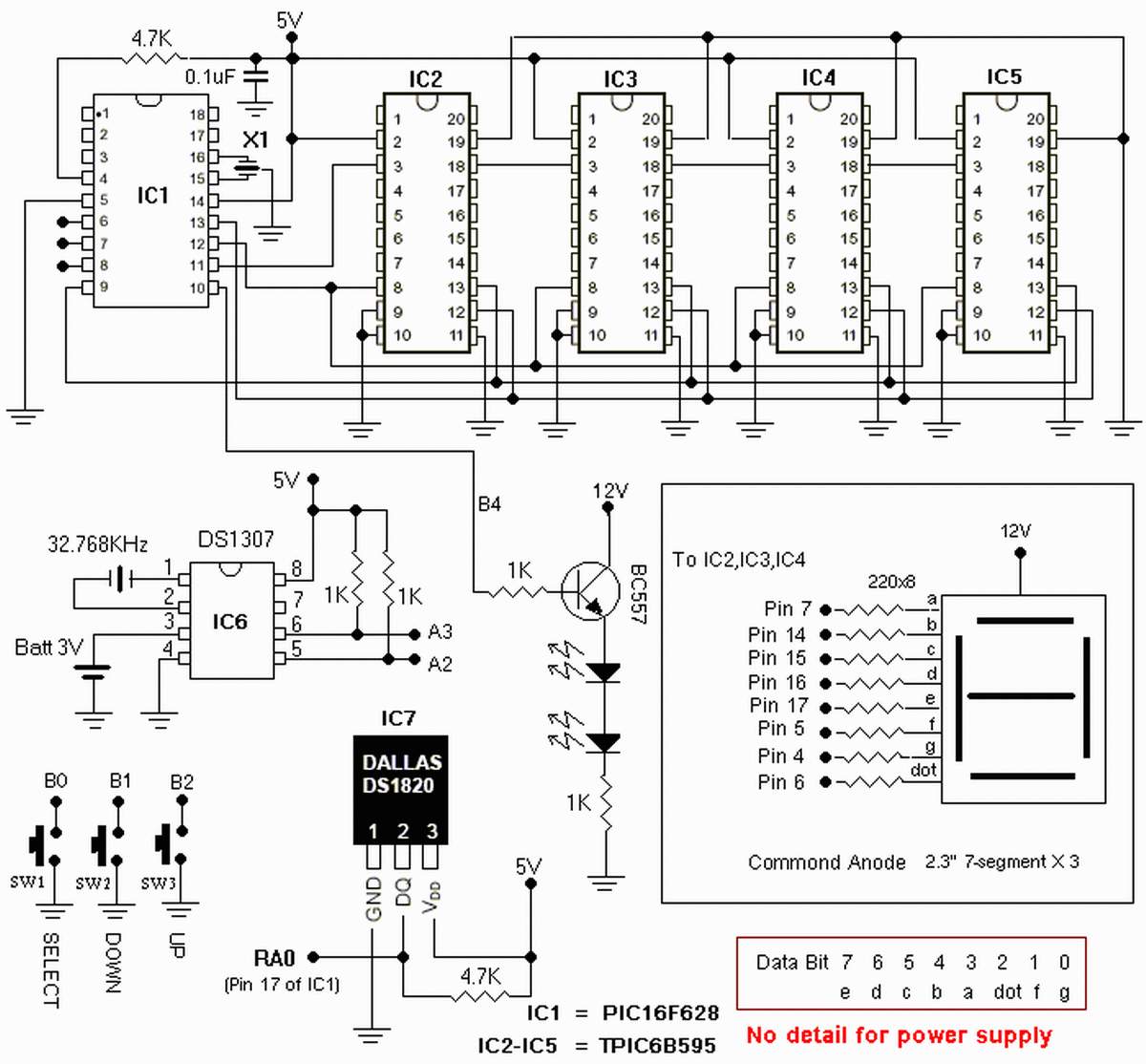
The clock is based on the PIC16F877 microcontroller from Microchip Technology Inc., which performs all of the logic necessary to decode the MSF signal and display the time on twelve 7-segment displays. The circuit design incorporates the PIC16F877 microcontroller, a...
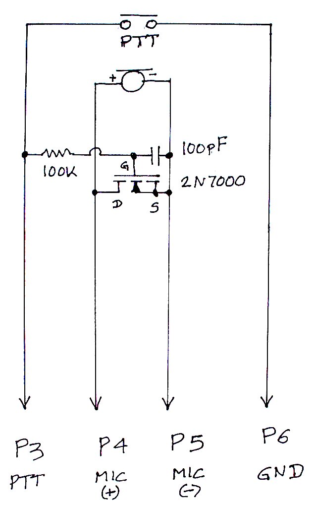
The TS-440S, similar to several other radios, does not mute the microphone when utilizing the rear audio connector for digital modes. Consequently, unless the microphone is unplugged each time digital modes are used, background noise from the shack can...
The two drawings utilize the LM324 operational amplifier to create a low-voltage comparator. Resistor R1 is part of a voltage divider circuit, while operational amplifier A1 is configured to a reference voltage level U1. Resistor R2 forms another voltage...
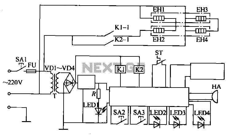
The circuit operates by activating switch SA1, which powers a 220V transformer that converts AC voltage to DC through a bridge rectifier, supplying power to the computer control panel. The temperature for cooking food is set on this control...
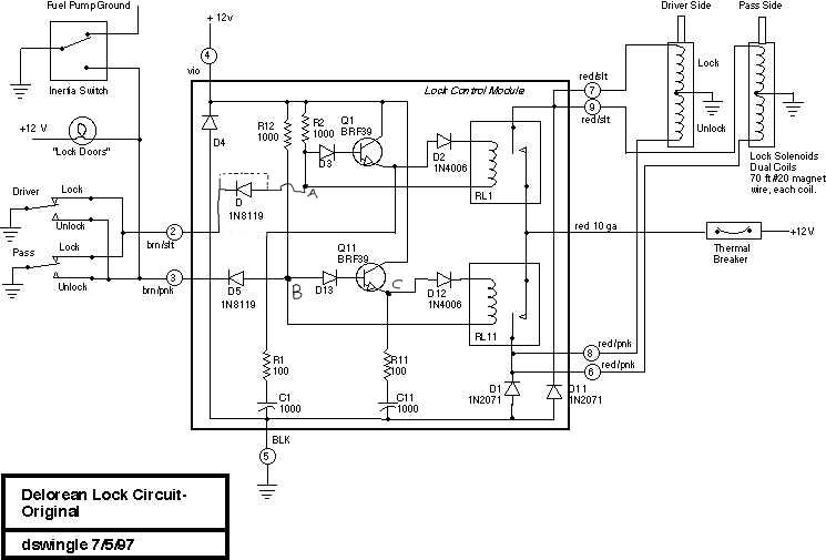
This document discusses the enhancement of a lock control module, providing instructions and photographs for upgrading the module to minimize its standby current consumption, thereby extending battery life. It is assumed that the user possesses a basic level of...
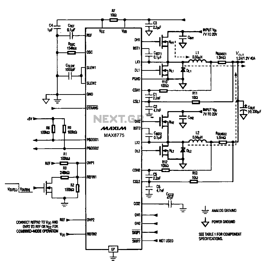
Notebook computer chip power supply circuit, which generates the PWM circuit using MAX8775. The notebook computer chip power supply circuit utilizes the MAX8775 integrated circuit to generate a Pulse Width Modulation (PWM) signal. The MAX8775 is a high-efficiency step-down voltage...
Warning: include(partials/cookie-banner.php): Failed to open stream: Permission denied in /var/www/html/nextgr/view-circuit.php on line 713
Warning: include(): Failed opening 'partials/cookie-banner.php' for inclusion (include_path='.:/usr/share/php') in /var/www/html/nextgr/view-circuit.php on line 713