
FM Transmitter Circuits - Best Of

The MAX260x series oscillators are particularly suitable for applications requiring stable RF signals in the specified frequency range. Their design enables easy integration into various transmitter setups, making them ideal for both hobbyists and professionals. The low-power FM transmitter schematic provides a clear pathway for constructing a working device capable of broadcasting audio signals. The use of surface-mount technology minimizes space requirements and enhances the overall compactness of the design.
The inclusion of an electret microphone allows for effective audio modulation, making the transmitter versatile for different audio sources. The FM spy transmitter example demonstrates the practical application of these components in a small, effective device with a reasonable range for personal use. The option to enhance transmission power with additional amplifiers expands the usability of the circuit, catering to various user needs.
The USB FM transmitter design represents a modern approach to audio broadcasting, allowing seamless integration with digital audio sources. Its harmonic-free operation and stability make it suitable for home use, providing a reliable solution for streaming music through standard FM radios without the complexities of traditional coil-based designs.
Overall, the MAX260x series and associated transmitter designs represent significant advancements in compact, efficient RF transmission technology, appealing to a broad audience from amateur radio enthusiasts to professionals in the field.Maxim now has available a series of five integrated oscillator building blocks in the MAX260x series which cover the frequency range between 45 and 650 MHz. The MAX2606 covers the VHF band, although the frequency can only be varied by approximately ±3 MHz around the midrange frequency set by the coil L.
Let`s construct a low-power FM transmitterusing surface-mount devices (SMD) that will be received with a standard FM radio. Soldering surface mounted devices is not so hard and actually is quite easy. The figure below shows the schematic of the transmitter which consists of two stages: an oscillator and an output amplifier. Modulation is from an electret microphone but you can use a low power audio source. Take a look at this fm spy transmitter which can be used as a bug transmitter or as fm bug too. It uses a single IC 74F13, one coil, a capacitor, one trimmer, one resistor and ofcourse one electret mic.
This spy bug is so easy to build and can give you a total coverage range of about 3 to 5 meters. You may want to use a small 100mW amplifier to give a little extend transmission range so you can spy from other location. A simple USB FM transmitter that could be used to play audio files from an MP3 player or computer on a standard VHF FM radio by connecting it to an USB port.
The circuit use no coils that have to be wound. This USB transmitter can be used to listen to your own music throughout your home. This is very stable, harmonic free, long range fm transmitter circuit which can be used for fm frequencies between 88 and 108 MHz. It has a very stable oscillator because you use LM7809 stabilizer which is a 9V stabilized power supply for T1 transistor and for frequency adjustment that can be achieved by using the 10K linear potentiometer.
The output power of this long range rf transmitter is around 1W but can be higher if you use transistors like KT920A, BLX65, BLY81, 2N3553, 2SC1970, 2SC1971. A very good 1 watt fm transmitter circuit, very easy to build circuit. It has 4 transistors, one is a very stable oscillator, followed by a buffer stage to prevent frequency variation when you adjust the transmitter.
Next is a resonance stage and the final stage built with a minimum 1W transistor which must have a heatsink. great advice : if you are thinking about becoming a pirate use a link transmitter that the radio authorities can`t intercept.
U may need a couple of throw away computers and internet connections could always come in handy too just a note, i have read all the posts. there are some of you that will need to make a UV light box`s and get the relavent bits and bobs (again see sm0vpo.
com) or try and get some pressnpeel circuit print/b/w laser printer needed. A drill stand is also pretty use full. RF circuitry is fickle, it`s not hard if you have some idea of radio building principles tho. Ladies and gentlemen, I have been leafing through the information on this page, and I find myself accosted with terrible english. This page is rife with grammatical discord, verbal variance, and overall poor vocabulary. I appreciate the assistance those with knowledge are attempting to give those without, but I beg of you, run your posts through spellcheck before finally posting.
I don`t want to complain about scraping` instead of scrapping, having an it`s and its discussion, tell people you can`t get a lysanse` for anything, to be more specific` instead of pacific`, etc. Your point may be correct, but your improper use of the very language you use makes you seem a fool. Invest the time to learn a more full control of your language, you`ll notice people regarding you as far more intelligent, you will stand out.
🔗 External reference
Related Circuits
This schematic represents an FM transmitter capable of delivering an output power of 3 to 3.5 W, operating within a frequency range of 90 to 110 MHz. While the stability of the circuit is acceptable, the integration of a...
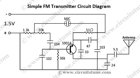
This is a simple FM transmitter circuit schematic diagram that utilizes a single transistor, S9014. The FM transmitter circuit operates by modulating an audio signal onto a carrier frequency, which is typically in the FM band. The S9014 transistor serves...

This circuit is a simple -5V power supply using a 555 timer, designed for low-power analog applications involving FET operational amplifiers. The circuit converts +5V to -5V to create a dual power supply. It operates as a 555 astable...

The previous tutorials on SPICE simulation in Fedora Electronic Lab have introduced various concepts. This post focuses on Part 3, assuming familiarity with gschem and completion of a course on analog electronic circuits. It is advised to review the...
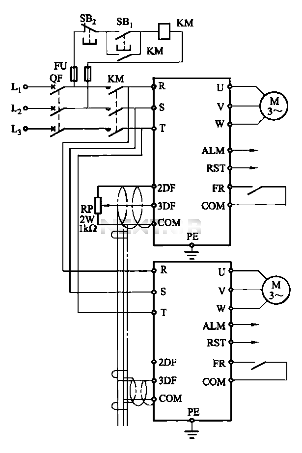
Each motor operates with an independent drive; however, only one frequency is utilized for a specific device. This setup employs a single RP potentiometer to control multiple motors in parallel. In this configuration, the circuit design allows for multiple motors to...

This page presents soft power switch circuits designed for toggling electronic devices ON and OFF with a momentary button press that controls a latching high-side MOSFET power switch. Multiple micropower latching switch circuits are included. Due to their low...