
Circuit diagram 500mW FM PLL transmitter 88-108MHz using LMX3206 and PIC16F870
The Colpitts oscillator is a type of LC oscillator that utilizes a combination of inductance (L) and capacitance (C) to generate oscillations. The unique configuration of the Colpitts oscillator allows for the generation of stable frequencies, making it suitable for applications in RF transmission and signal processing. The choice of the BC817 transistor, while not an HF transistor, serves as a practical solution for low-cost applications, but may limit the frequency range and performance compared to higher-grade transistors.
The LC tank circuit consists of a capacitor and inductor, which resonate at a specific frequency determined by their values. The frequency of oscillation can be calculated using the formula:
\[ f = \frac{1}{2\pi\sqrt{LC}} \]
In this configuration, the modulation capabilities are enhanced by the integration of the 74HC4020 binary counter. This device enables frequency division, allowing the output signal to be manipulated for various applications. The use of a potentiometer for modulation depth provides flexibility in tuning the oscillator for different signal requirements, which is a critical aspect in communication systems where signal clarity and bandwidth are essential.
The resistors R1 and Re2 play a pivotal role in controlling the biasing and stability of the transistor, ensuring that the oscillator operates within the desired parameters. The suggested values for these resistors are based on empirical testing, and adjustments may be necessary depending on the specific circuit conditions and desired output characteristics.
Overall, the Colpitts oscillator circuit described offers a versatile platform for generating frequency-modulated signals, with the potential for further enhancements and modifications based on user requirements and application scenarios.This oscillator is called the Colpitts oscillator and voltage controlled to achieve the FM (frequency modulation) and PLL control. T1 must be HF transistors to work well, but in this case I use a cheap and common BC817 transistor. LC tank oscillator needs to oscillate properly. (I must warn you that the signal is not symmetrical in form. Pulsa pos itive only a few microseconds, so you will be hard to see on the oscilloscope. ) I solved by connecting it to 74HC4020 (14-stage Binary Counter) to input pin 10 Hours. In Q0 (pin 9) you will have a symmetrical square wave with a frequency half since the circuit is a table. In Q1 pin 7 will be divided by 4, see data sheet for more information. A potentiometer P1 was added to adjust the depth of modulation (FM Wide or Narrow FM). You may have to play a bit with a value of P1 because it tends to modulate the lot. You may need to add the 500k 1M potentiometer only. You test and find out for himself. Resistor R1 and resistor Re2 regulate the flow of DC. In this case I find that 9. 1k will give a good output power and thus equal to 150. If you want to increase the power should be lower Re2. You can add another 150 ohm resistor in parallel. 🔗 External reference
Related Circuits
A simple transistor generator and transformer converts a 1.5V battery voltage to several hundred volts. This high voltage current then passes through a diode, which rectifies the current to DC. This DC current is stored in a relatively large...
A highly beneficial project involving a crystal tester circuit, also known as an xtal tester circuit, constructed with only a few components. The circuit forms an oscillator that will only oscillate if the crystal under test is functioning properly....
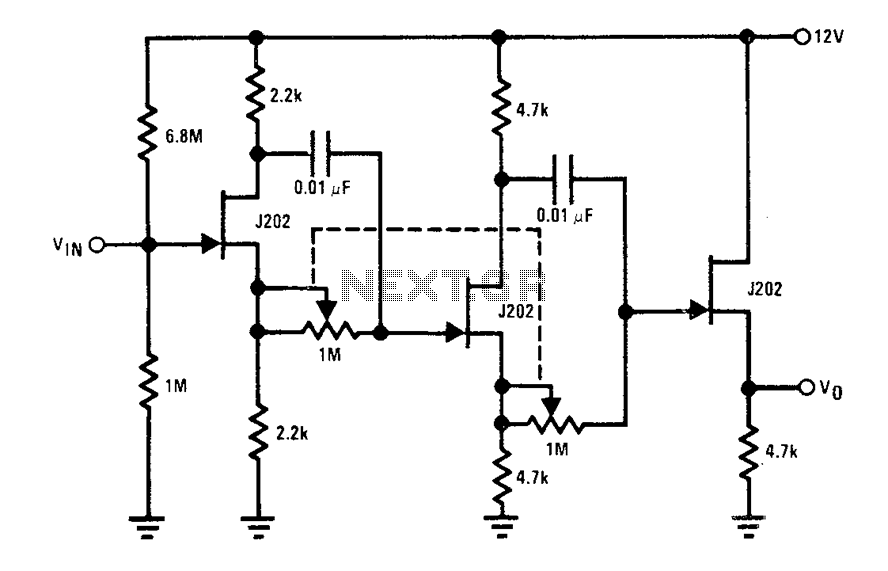
Each J202 JFET stage provides up to 180 degrees of phase shift controlled by a 1 megohm potentiometer. The potentiometer allows for complete control of the groups. JFETs are ideal for the designated circuit because they do not load...
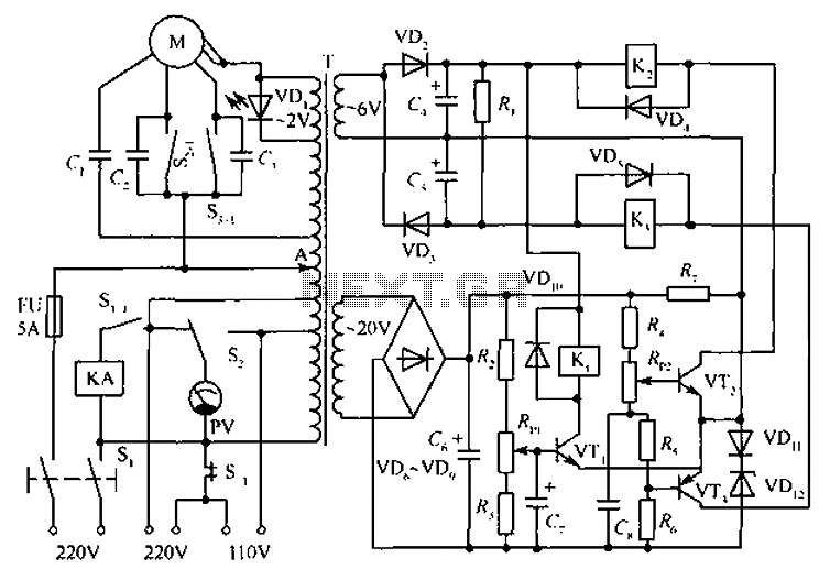
The circuit depicted in the figure includes an automatic voltage regulator (T) that maintains a constant output by utilizing a servo motor. The circuit features transistors VT1 and VT2 (3DK9), with a capacitance range of C (65 ~ 85)....
This project utilizes an LM338 adjustable three-terminal regulator to deliver a current of up to 5A with a variable output voltage ranging from 2V to 25V DC. It is particularly useful for powering various electronic circuits during the assembly...
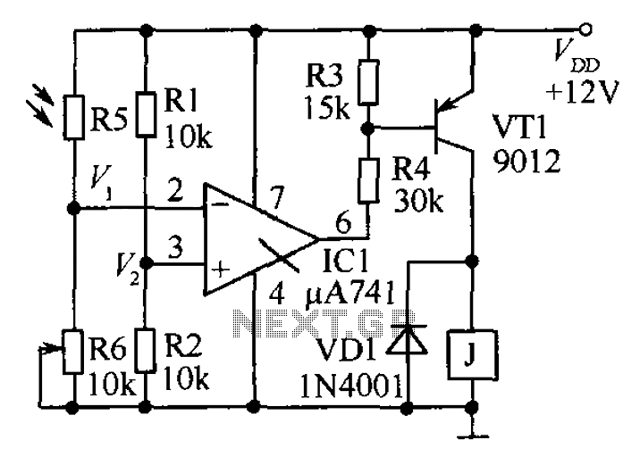
The circuit functions as a precision bright light control circuit, operating independently of power supply voltage and ambient temperature. Resistors R1, R2, R6, and the photosensitive resistor R5 form a two-arm Wheatstone bridge. The precision bright light control circuit utilizes...
Warning: include(partials/cookie-banner.php): Failed to open stream: Permission denied in /var/www/html/nextgr/view-circuit.php on line 713
Warning: include(): Failed opening 'partials/cookie-banner.php' for inclusion (include_path='.:/usr/share/php') in /var/www/html/nextgr/view-circuit.php on line 713