
fm wireless microphone circuit
The FM wireless microphone circuit is designed to provide a reliable and efficient means of audio transmission over a considerable distance. The simplicity of the design makes it accessible for hobbyists and engineers alike, while the specified component values ensure optimal performance. The audio amplifier stage (T1) is crucial for amplifying the microphone's signal, which is then modulated onto an RF carrier frequency by the LC tank circuit (T2). The choice of a common emitter configuration for T1 allows for a good balance of gain and bandwidth, facilitating clear audio transmission.
The design utilizes a feedback capacitor (C5) to stabilize the oscillation of the LC tank circuit, which is essential for maintaining a consistent frequency output. The parallel LC circuit formed by L1 and C4 is critical for tuning the transmitter to the desired frequency within the FM band. Adjusting the distance between the coils allows for fine-tuning of the transmission frequency, which is particularly useful for avoiding interference with other radio signals.
The antenna design is another vital aspect of the circuit. The specified lengths of 150 cm or 75 cm for half or quarter wavelengths, respectively, ensure optimal radiation of the RF signal, maximizing transmission range and clarity. The coupling capacitor (C6) plays a significant role in transferring the amplified signal to the RF amplifier (T3), which further enhances the strength of the transmitted signal.
For calibration, the recommended practice of positioning the transmitter close to an FM radio helps in fine-tuning the setup. By adjusting the coil L1 while monitoring the radio's reception, users can achieve the best possible performance from the microphone system. Overall, this FM wireless microphone circuit exemplifies an effective combination of simplicity and functionality, making it a valuable project for those interested in wireless audio transmission.This FM wireless microphone is easy to build and has a large benefit of transmission (about 300 meters, while outdoor). Regardless of its small component count and 3V operating voltage that will easily penetrate the excess of some floors of an apartment development.
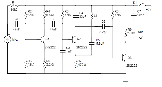
It can be adjusted everywhere, while in the FM band (87-108MHz) and its transmissi ons can be picked up at any ordinary FM receiver. The coil (L1) should be about 3 mm in diameter, with five rounds of 0. 61 mm copper wire. You are able Tx frequency range by simply adjusting the distance between the coils. The antenna should be half or quarter of an extended wave (100 MHz 150 cm or seventy-five centimeters). FM wireless microphone circuit The audio amplifier stage (T1) is a conventional common emitter amplifier.
The 47nF capacitor isolates the microphone from the base voltage to the transistor and only allows AC signals to pass. The LC tank circuit T2 occurs, the feedback capacitor C5 and the parallel LC circuit L1, C4. The coupling capacitor (C6) directs the signal to your amplifier RF (T3). FM Wireless Microphone calibration circuit: Location of the transmitter 10 feet of a FM radio. Place the radio in a 89 to 90 MHz Spread the coil in the coil L1 frequency tuning also sought. 🔗 External reference
Related Circuits
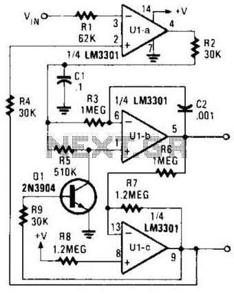
The Phase-Locked Loop (PLL) will synchronize with an input signal, providing both triangle and square wave outputs. A quad operational amplifier can be utilized in this circuit, making it suitable for audio and low-frequency radio applications. The Phase-Locked Loop (PLL)...
This wireless headphone transmitter ensures a reliable connection over a distance of 2 meters. The oscillator frequency ranges between 1750 KHz and 3500 KHz, utilizing a ferrite bar as the antenna. IC1 amplifies the audio signal, while TC1 serves...
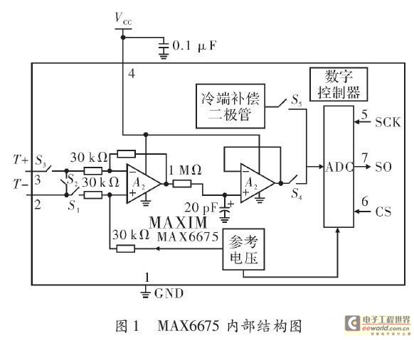
The K-type thermocouple is a commonly used temperature sensor in industrial production and scientific experiments. It can measure temperatures ranging from 0 to 1300 degrees Celsius in various applications, including direct measurements of gas, liquid, and solid surfaces. Its...
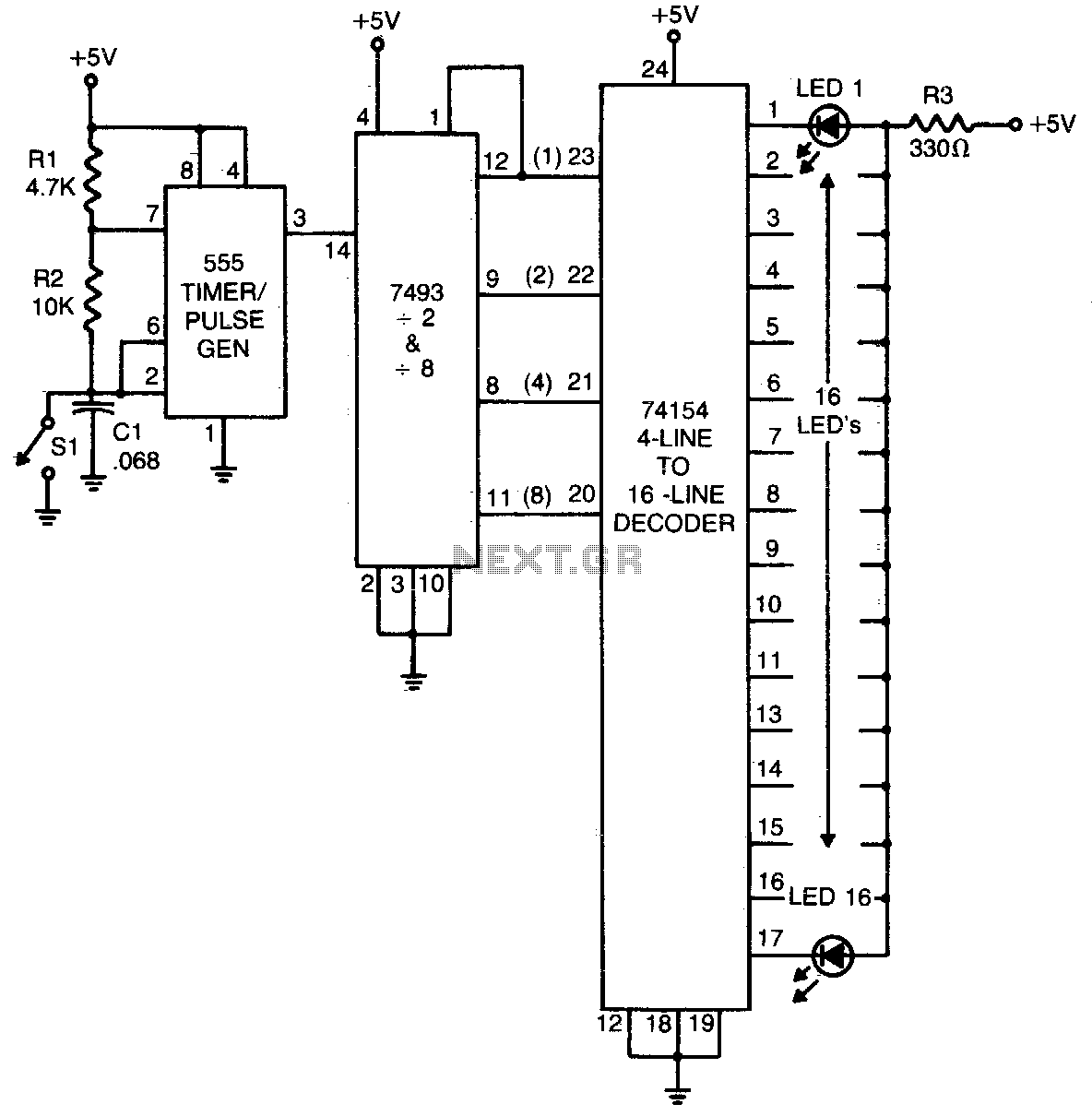
The 555 timer generates a rapid series of pulses when switch SI is in the open position. These pulses are grouped into sets of 16 and converted into binary format by the 7493 counter. The binary output is then...
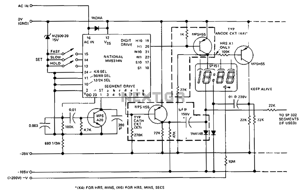
A CMOS clock circuit is capable of driving a multi-digit gas discharge display. This simple circuit does not include an alarm feature but allows for a flashing colon to indicate morning and afternoon. The circuit requires seven drive circuits...
This circuit utilizes a single 555 Timer IC and a small transformer to generate high voltage for testing zener diodes with voltage ratings up to 50VDC. The 555 timer operates in astable mode, with the output at pin 3...