
Four gas monitor circuit diagram

The CMOS clock circuit operates using complementary metal-oxide-semiconductor technology, which is known for its low power consumption and high noise immunity. The design includes a multi-digit gas discharge display, where each digit is illuminated by gas discharge, providing a bright and clear visual output.
The circuit's simplicity lies in its ability to manage the display without complex components or features. The flashing colon serves as a visual indicator for AM and PM, enhancing the functionality of the clock without the need for an alarm system.
In terms of the driving circuits, seven are required to properly manage the display, with the digital driver circuit playing a crucial role in controlling the operation of the gas discharge display. Although only two circuits are actively used for displaying the time, the additional circuits are essential for ensuring that the display operates correctly and can handle the necessary voltage and current levels.
For applications requiring the display of seconds, an extra drive circuit is mandated. This additional circuit allows for the integration of a second display or the enhancement of the existing display to show seconds alongside hours and minutes.
Overall, the CMOS clock circuit is an effective solution for timekeeping applications that require a simple yet functional display system. Its design ensures reliability and ease of implementation, making it suitable for various electronic projects. CMOS clock circuit can drive a multi-digit gas discharge display, simple circuit does not include an alarm, which can be flashing colon morning and afternoon show. The circuit need to use seven drive circuits and digital driver circuit, although only display two circuits among a. If you want to display seconds, then you will also need an additional drive.
Related Circuits
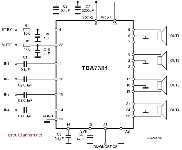
The amplifier is a quad amplifier circuit (amplifier with four inputs and four outputs) based on the TDA7381. This amplifier is designed for car audio systems, but it can also be utilized for other applications. The circuit has a...

This design outlines a high impedance DC voltmeter circuit utilizing the uA741 integrated circuit (IC). The uA741 is configured as a non-inverting DC amplifier. The circuit incorporates negative feedback through a DC meter that requires 1 mA for full-scale...
The schematic indicates that the AccelR8 utilizes only three integrated circuits (ICs). An AVR 8515 microcontroller performs the computational tasks and manages the other circuits. A MAX603 regulates voltage and controls the power-on and power-off functions. The key component...

The circuit for the RS232 serial interface exhibits mild complexity. The primary components of the circuit include the 18F4520 microcontroller, MAX233A level shifter, and a DB-9 connector. This circuit utilizes a basic +5V power regulator to supply the digital...
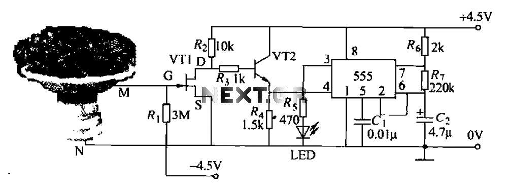
The flowers in pots require watering, as relying solely on the observation of moist soil surfaces can be unreliable. To address this issue, a flower watering indicator has been developed. This circuit includes a field effect transistor (VT1), a...
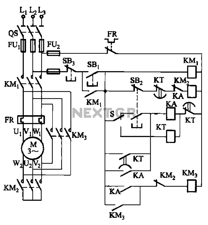
The circuit is depicted. It is capable of both manual and automatic control. The circuit in question is designed to facilitate dual modes of operation: manual and automatic control. This versatility allows users to engage with the system according to...